Table of Contents
- Summary
- Teardown
- Keybed
- The buttons
- Cleaning the Appearance
- Panel Board
- The Joystick
- Bender Board
- Power supply
- Main Board
- Final Assembly
Summary
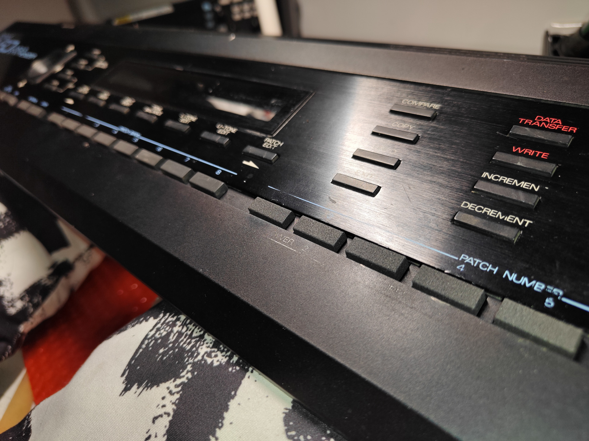
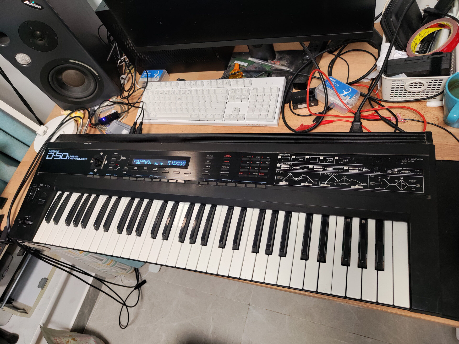
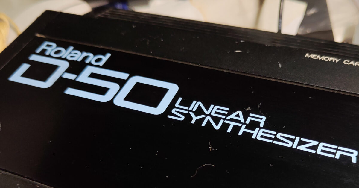
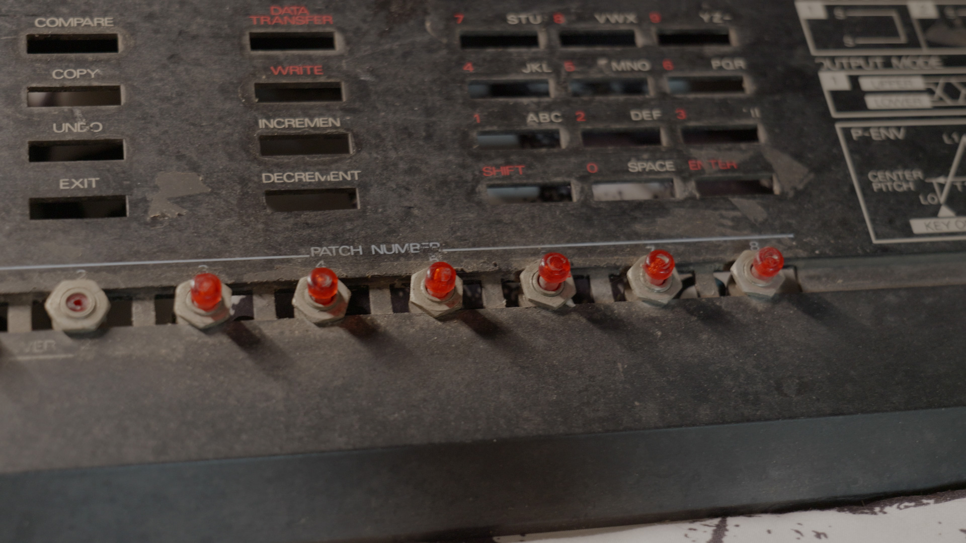
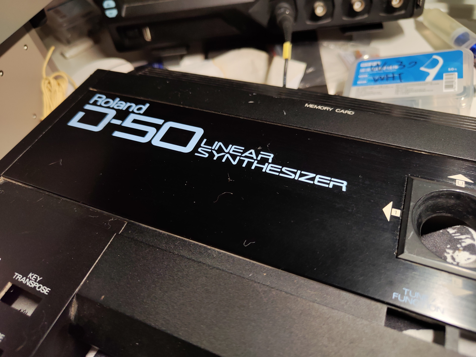
The Roland D-50 is a very famous synthesizer from the 1980s. Together with the Yamaha DX-7, those became the most well-known synth from that era. I got a D-50 from 闲鱼 for CNY 800 (USD~150). It powers on, buttons response but the seller has no way to test it further. The patch selections buttons are missing and were replaced with hacked-in pushbuttons.
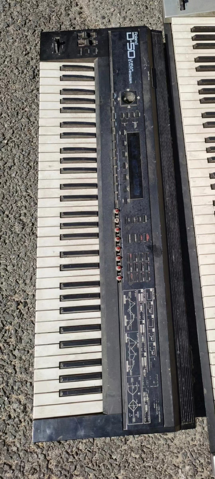
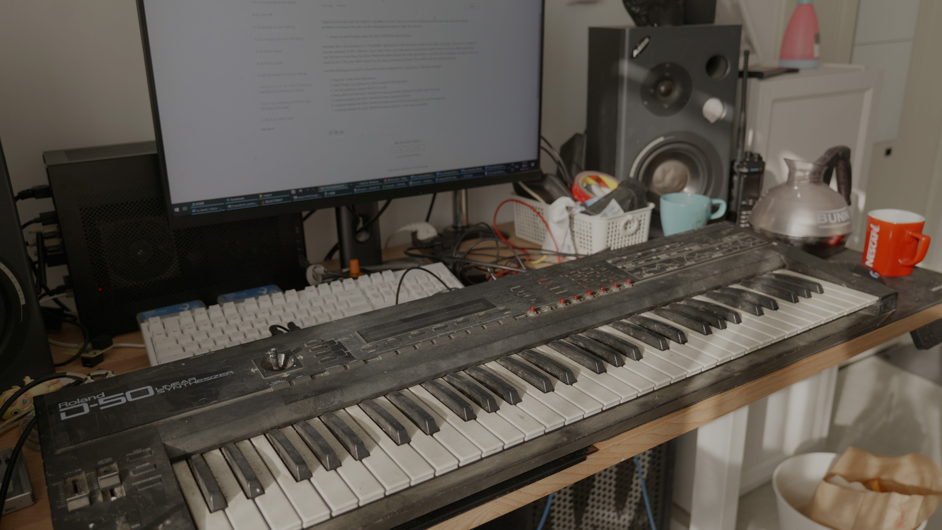
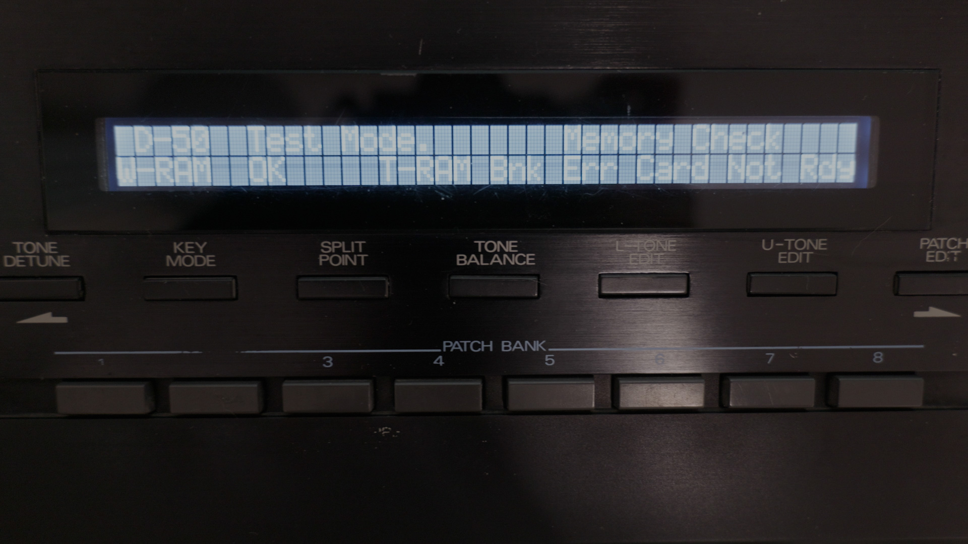
Upon arriving I found the unit to be extremely dirty. The outside is covered in stains. Unfortunately that’s only the start of it. Using normal and test mode I got list of parts that does not work, from left to right:
- Volume potentiometer does not work
- After touch does not register
- Bender only works in the positive range
- Modulation only registers about 30 out of 127 despite pressing really hard
- Joystick value jumps around
- About half of the keys does not work
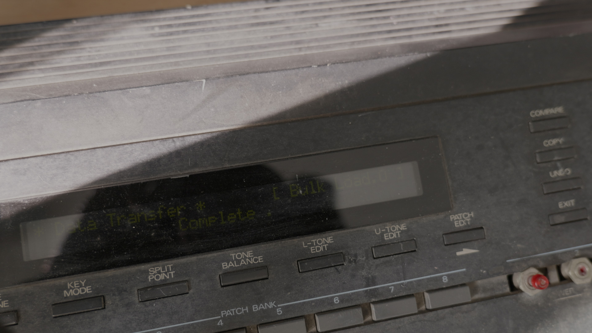
In addition, patch groups does not store correctly in the 1 to 5 bank. System settings also cannot be stored. In test mod T-RAM (Tone ram, the battery backed one) has a bank error.
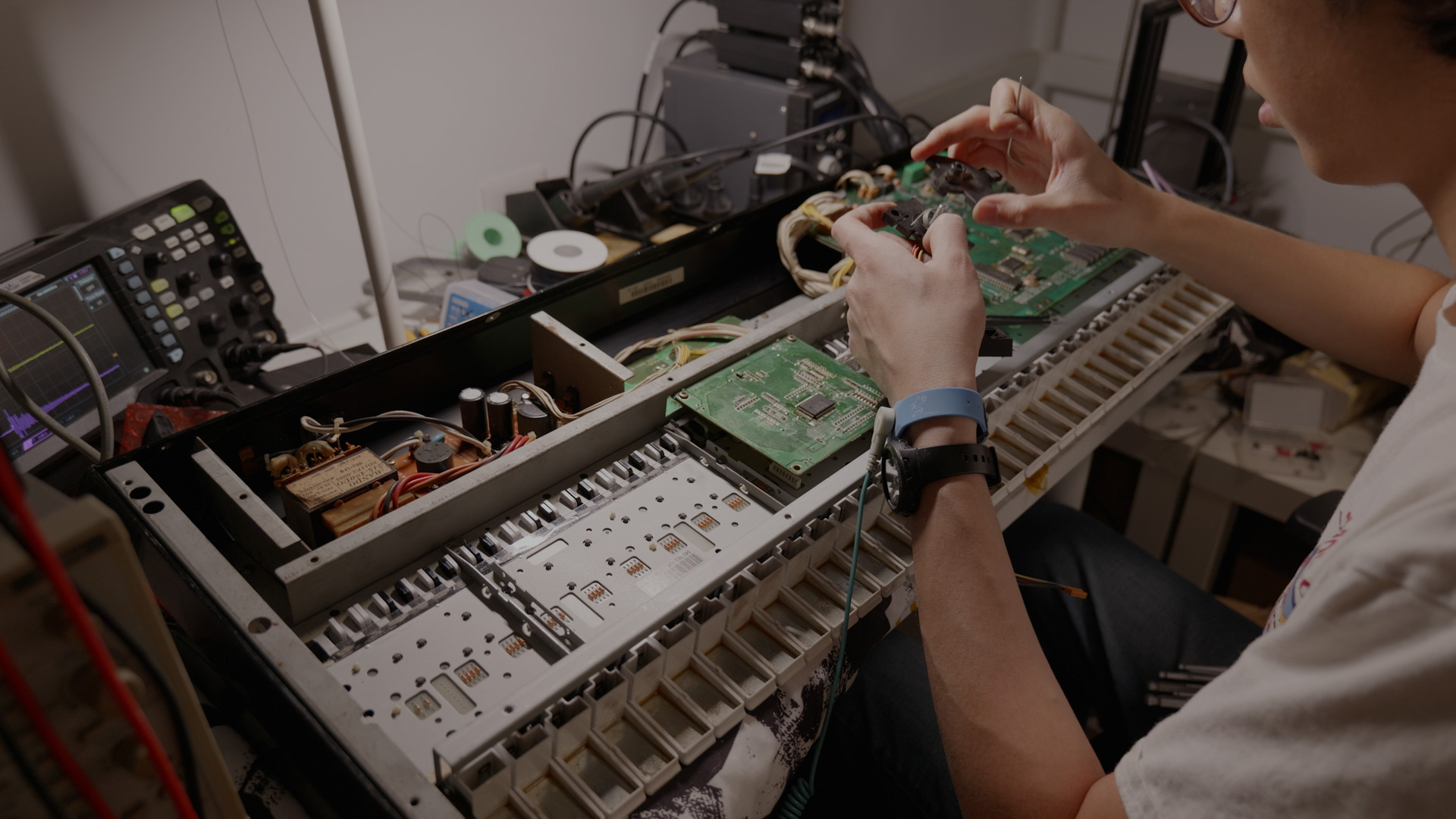
Using patches from banks that’s further back in the memory I was able to check the sound generation part. That is working fine, which is a big relief. So I started to tear down the unit and begin restoring it.
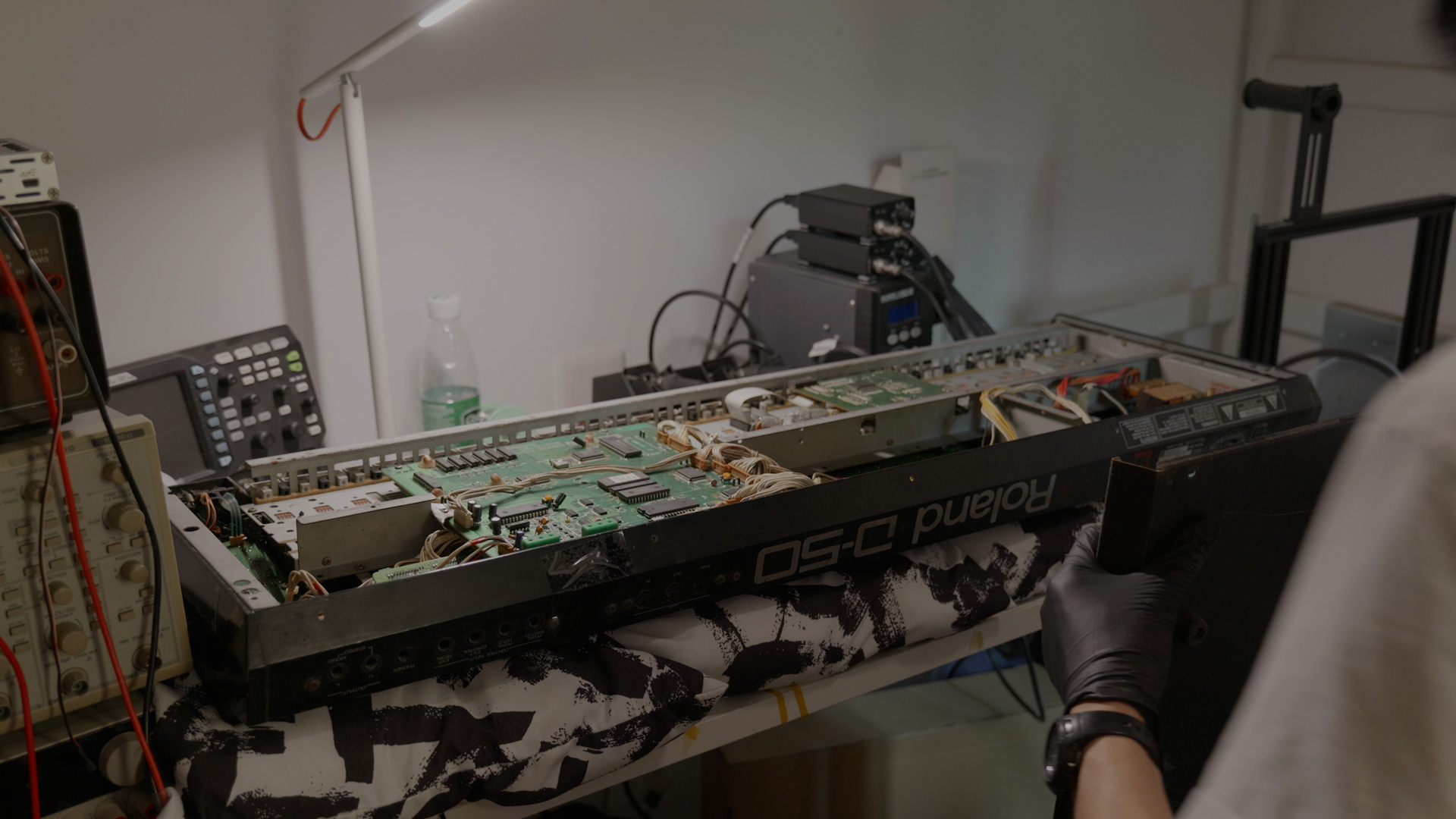
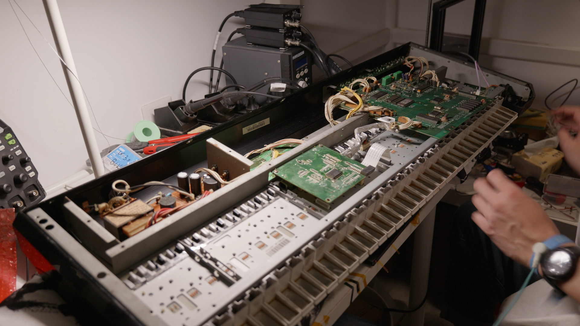
Teardown
All in all the unit is in good shape on the inside. The potentiometers are doomed due to water rust, and has been shorted by previous repair technician to maintain a stable audio output. The patch number switches has been removed and replaced with pushbuttons.
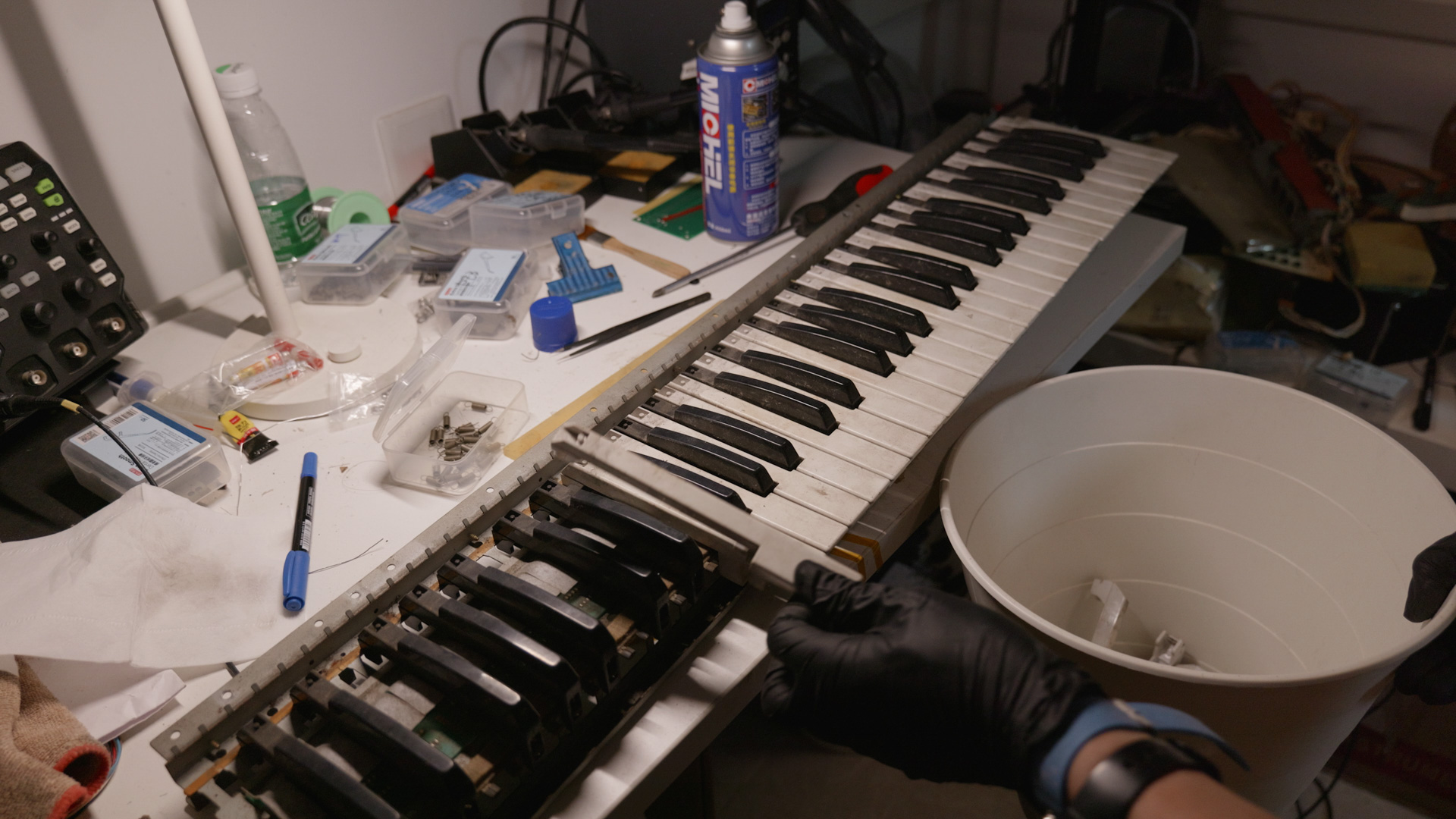
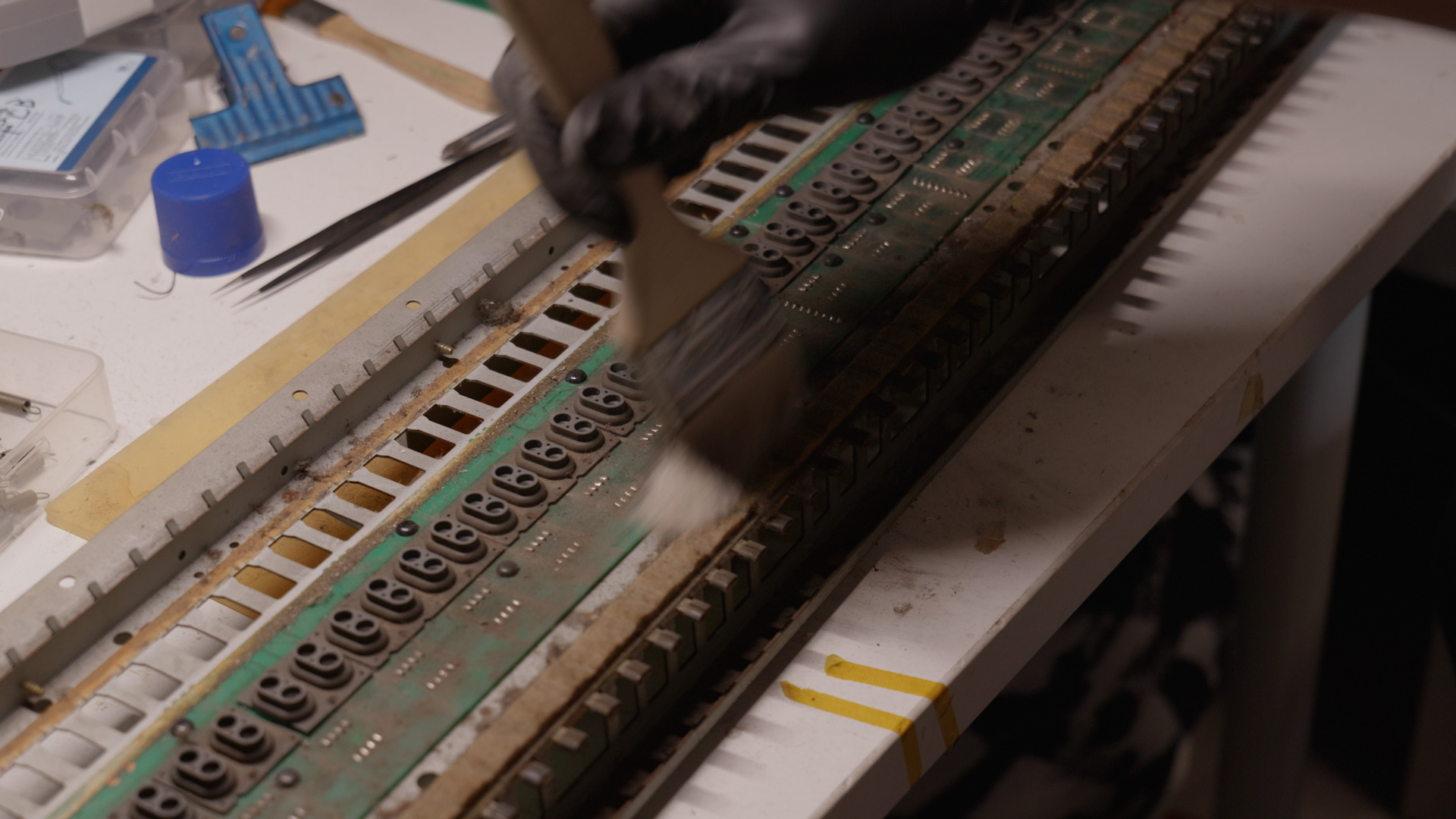
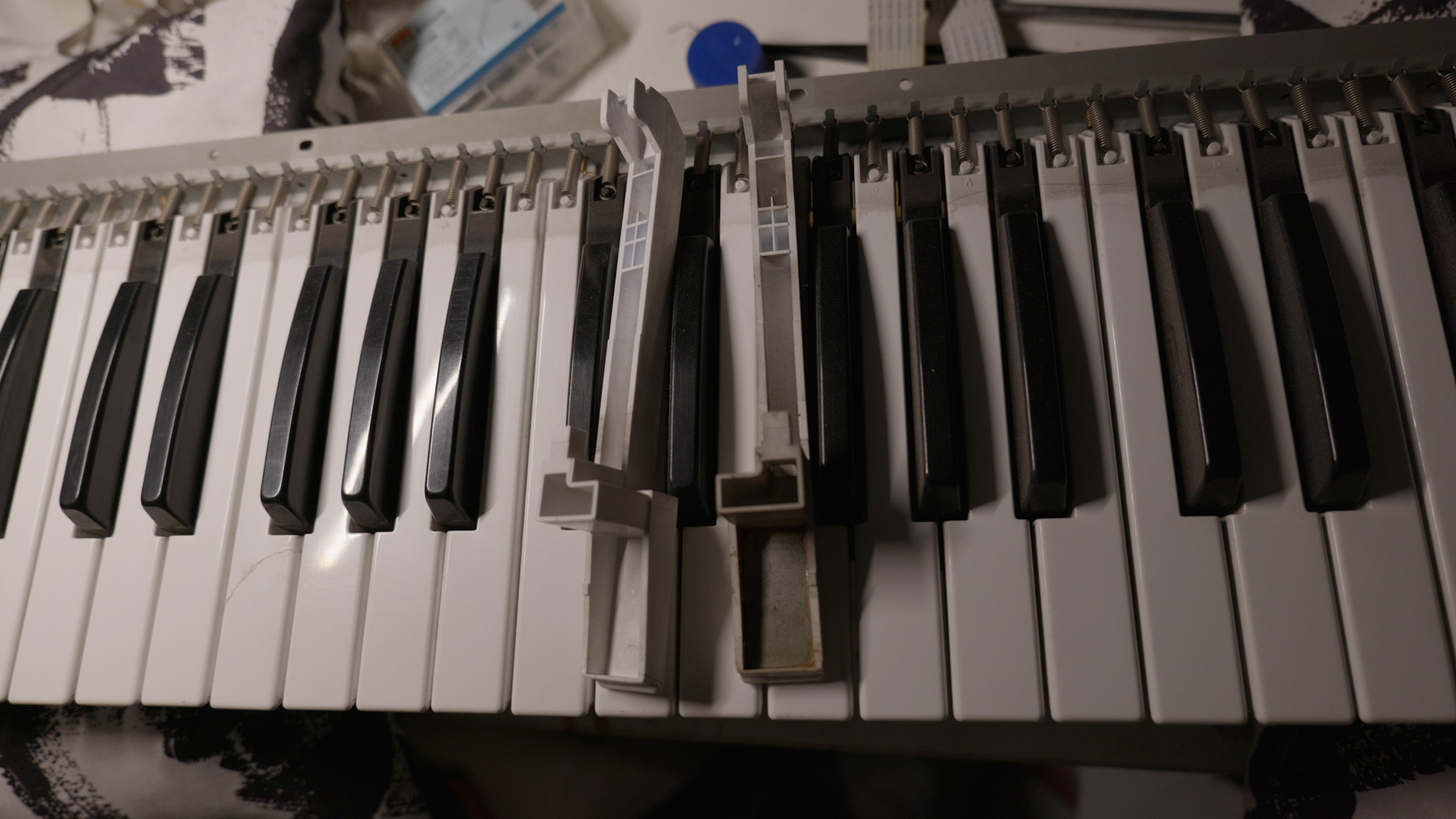
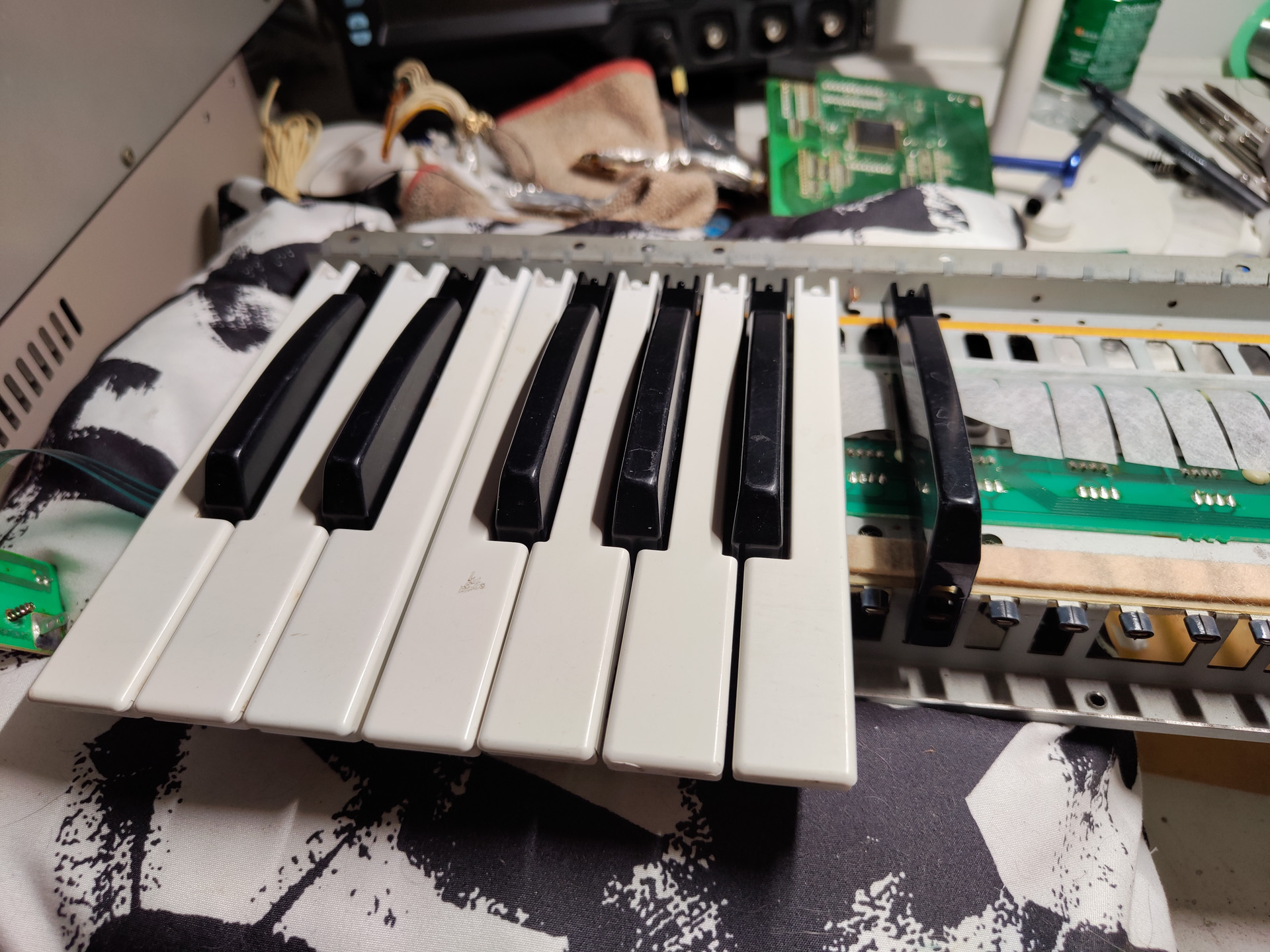
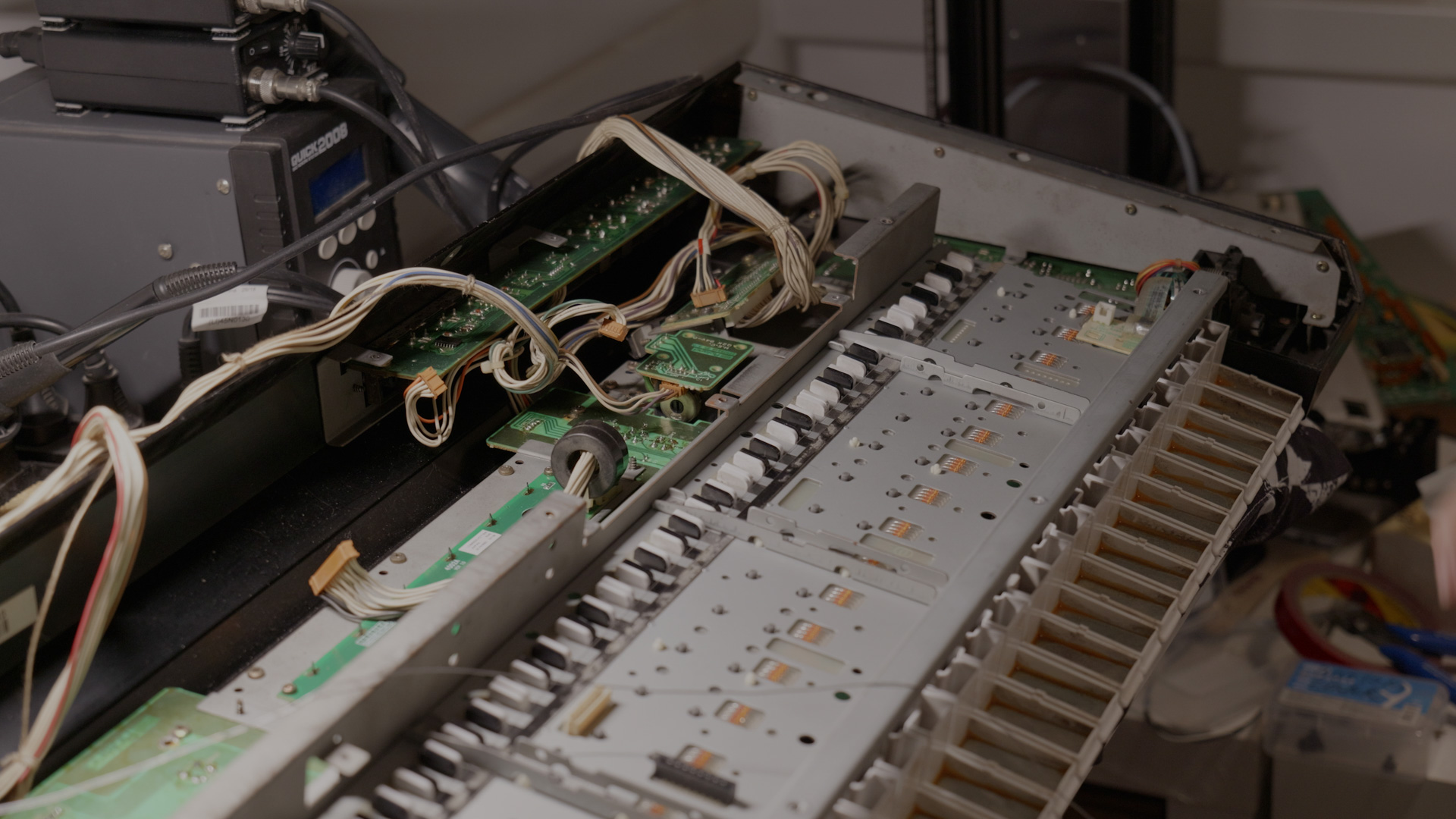
Keybed
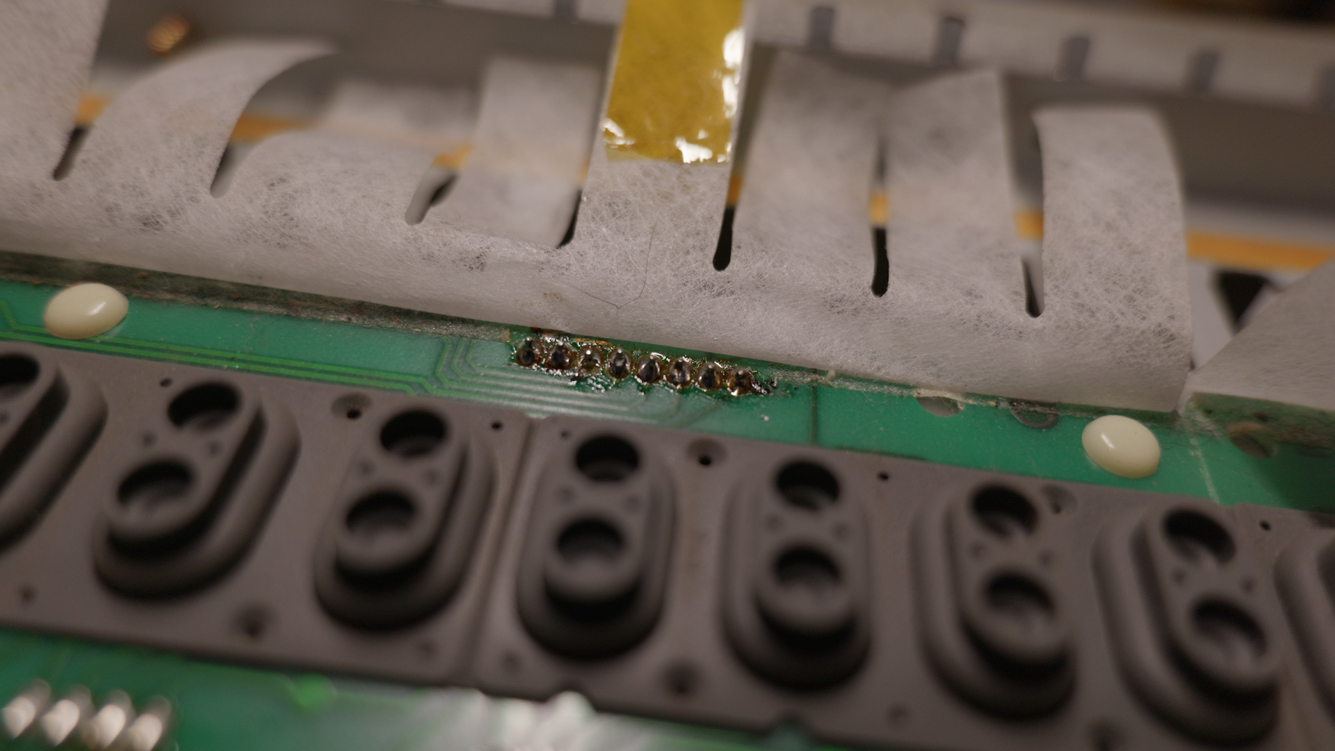
The keybed is the most dirty part, contains a lot of dust, and is very rusty. The conductive rubber part has all been cut up and put back in. Measurement shows a few of those does not work anymore.
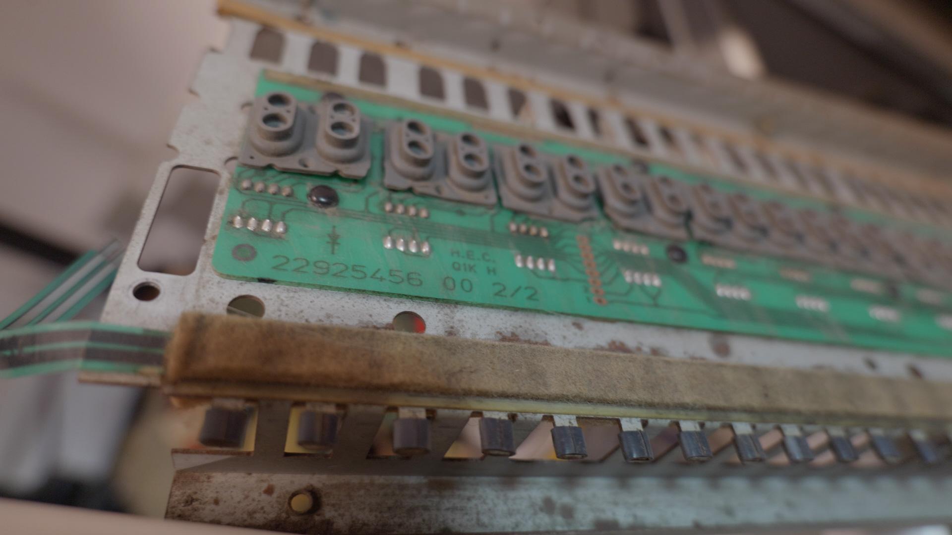
I have a W-30 laying around. It has a fried TVF chip so that machine is beyond repair. I decided to rebuild the keybed using the W-30 keybed. I can’t just put the W-30 keybed in because 1) the D-50 keys are weighted, 2) the keybeds use different connectors, and 3) they are different mechanically although mostly compatible.
The mounting hole pattern on the W-30 keybed (7621220000 SK-361-VR) and D-50 keybed (76180200 SK-361-PW) are identical. The W-30 keybed is missing some board supports but that can be fixed with either glued-in support or 3D printed standoffs. The PCB is identical with only the connector differing.
The plan was to use the frame of the D-50 keybed and move everything from the W-30 keybed to it and use D-50 keys. However after some searching I recognized that it’s a bad idea to transplant the aftertouch component from W-30 keybed. So I went with using W-30 keybed frame(with its aftertouch), PCB, springs, and D-50 keys.
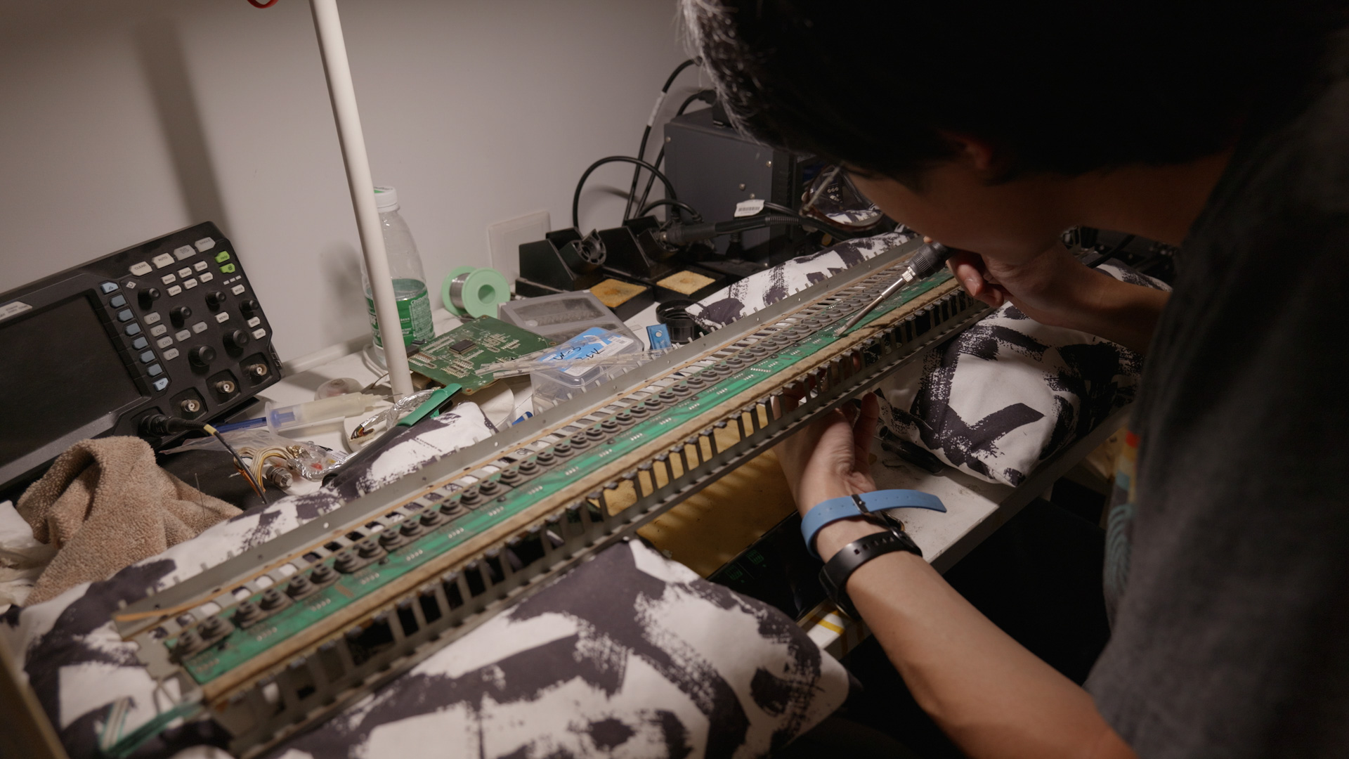
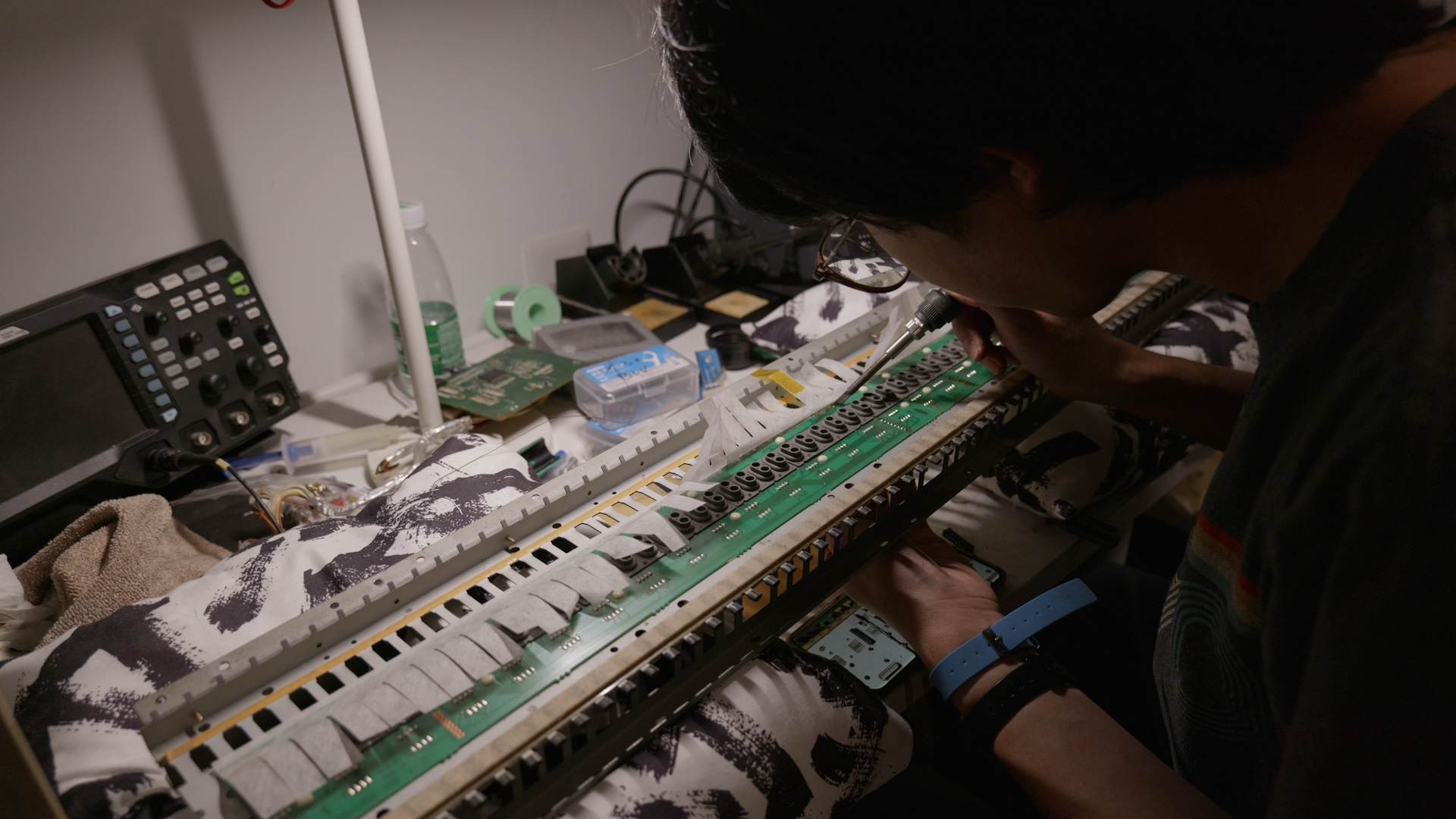
The first step is to remove a mounting strip from the D-50 keybed and mount it onto the W-30 keybed. Those keybed has a frame that’s almost the same, and can be fitted with different mounting strip to mount to different synths.
Next I moved the connectors from the D-50 keybed PCB to the W-30 keybed PCB where necessary.
The keys removed from the D-50 keybed were cleaned, scrubbed with baking soda, rinsed and dried
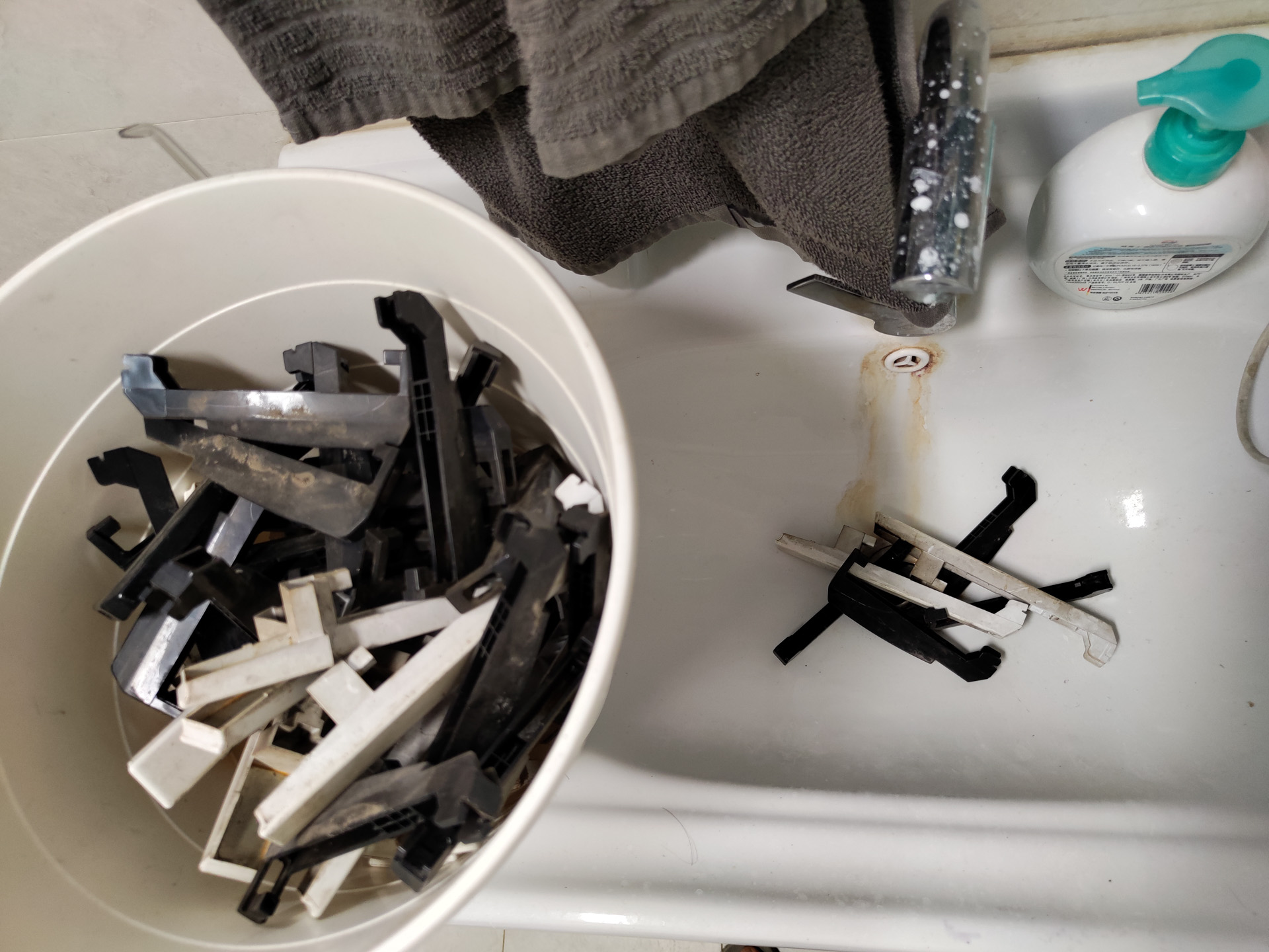
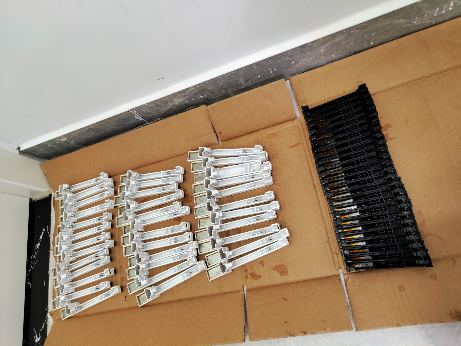
Then the whole keybed was reassembled, using the correct spring for white or black keys respectively.
The buttons
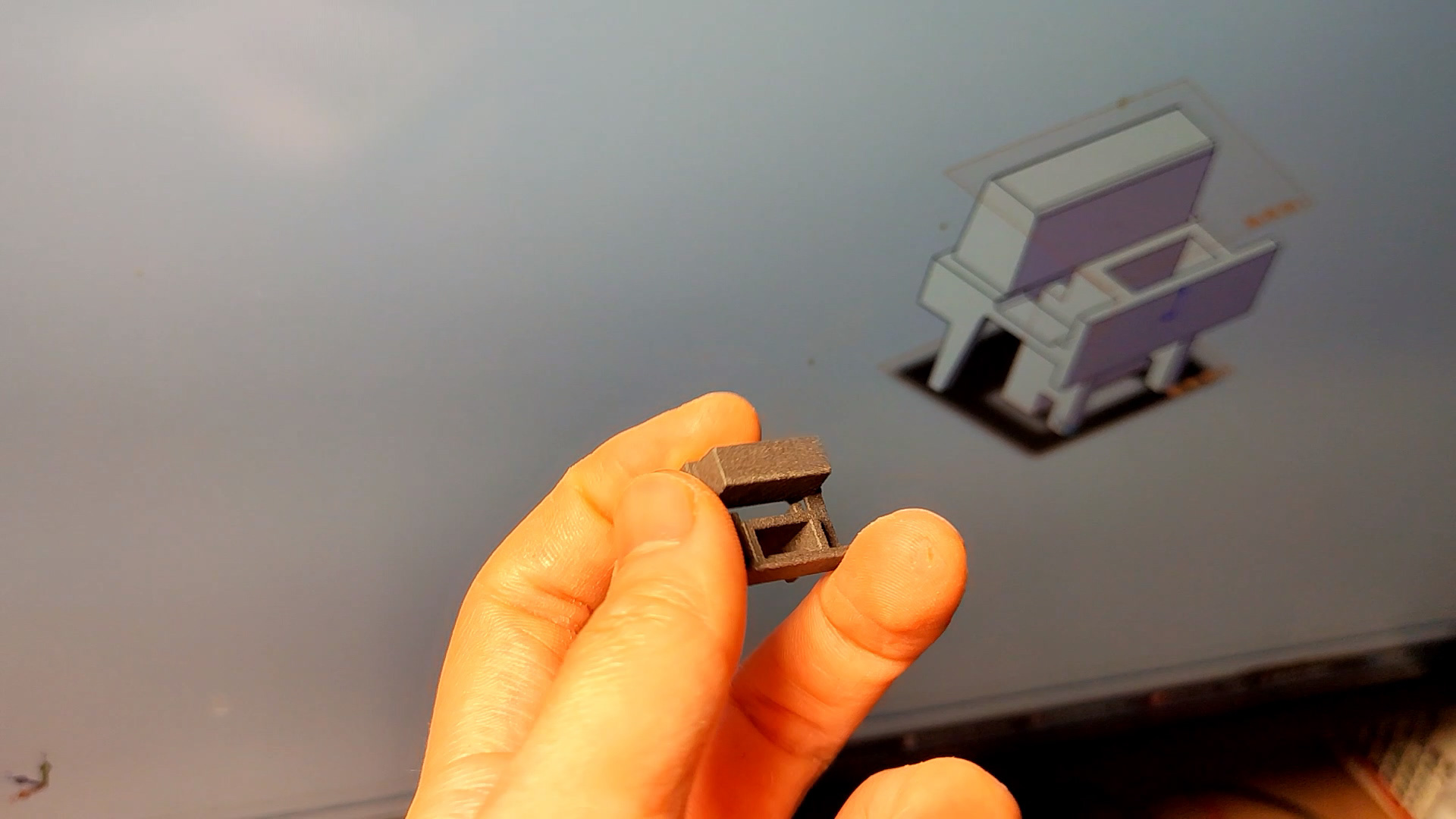
Since the previous repair discarded the plastic buttons (22475668), I had to make some new ones if I were to completely restore the D-50. So I traced out a 3D model of the keys, using a caliper and SolidWorks. This is a pretty complex injection molded part but luckily I do know something about mold design, dimension chain and tolerances etc. Also it didn’t have to be identical with the original. Good enough is good enough.
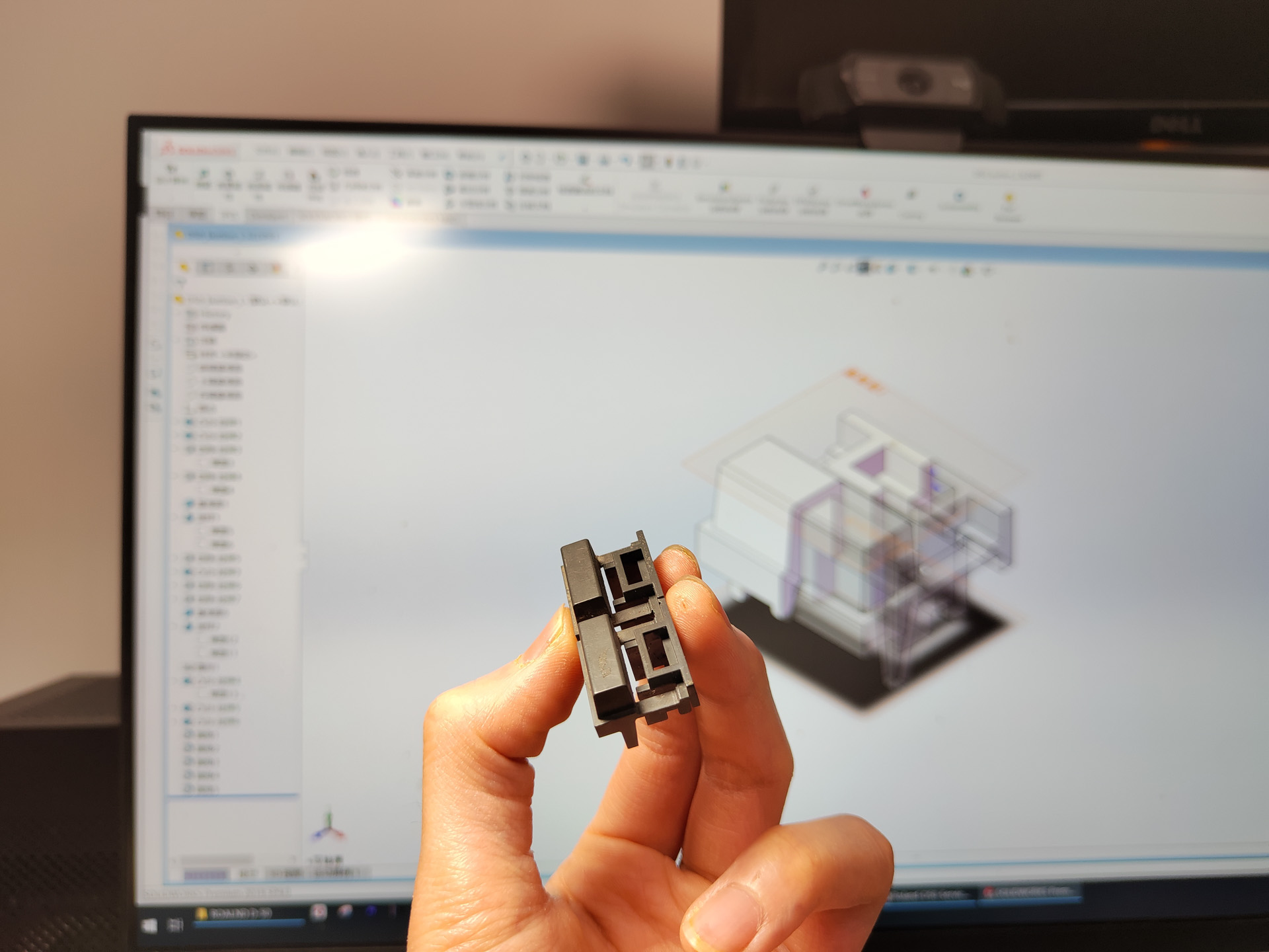
I sent the file out for 3D printing with Nylon SLS, since the shape is too complex to print with the single material Ender 3 I own. Using Nylon also ensures it will be durable enough for many years, and won’t melt in a car under direct summer sun like PLA. It came back a few days later and looks very nice with the matte SLS texture. A test assembling showed that it works perfectly.
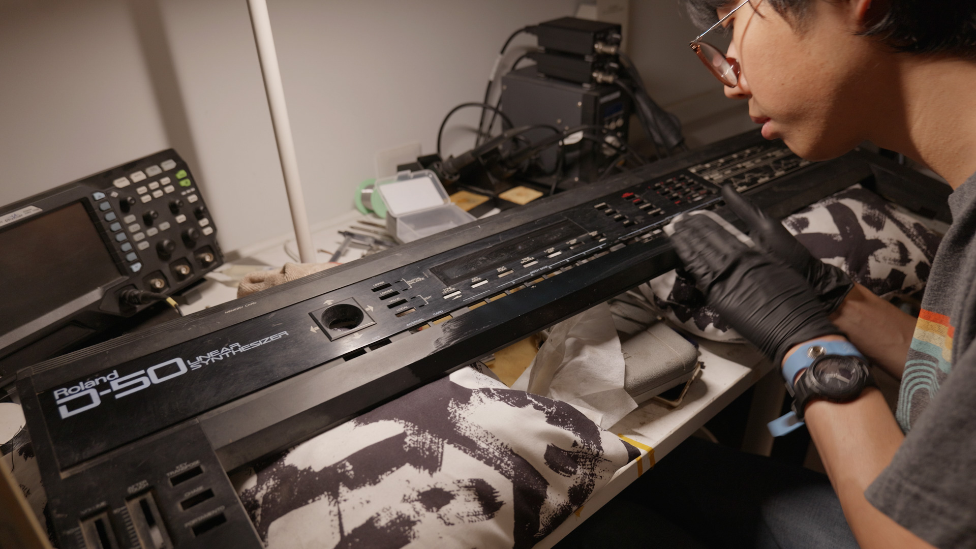
Cleaning the Appearance
The main panel is aluminum with matte and glossy finish. I tried regular stuff, water, dish soap, baking soda, none of those worked. In the end I had to use engine degreaser (contains lye, highly corrosive) to clean the outside stains. I also used adhesive remover to clean some tapes.
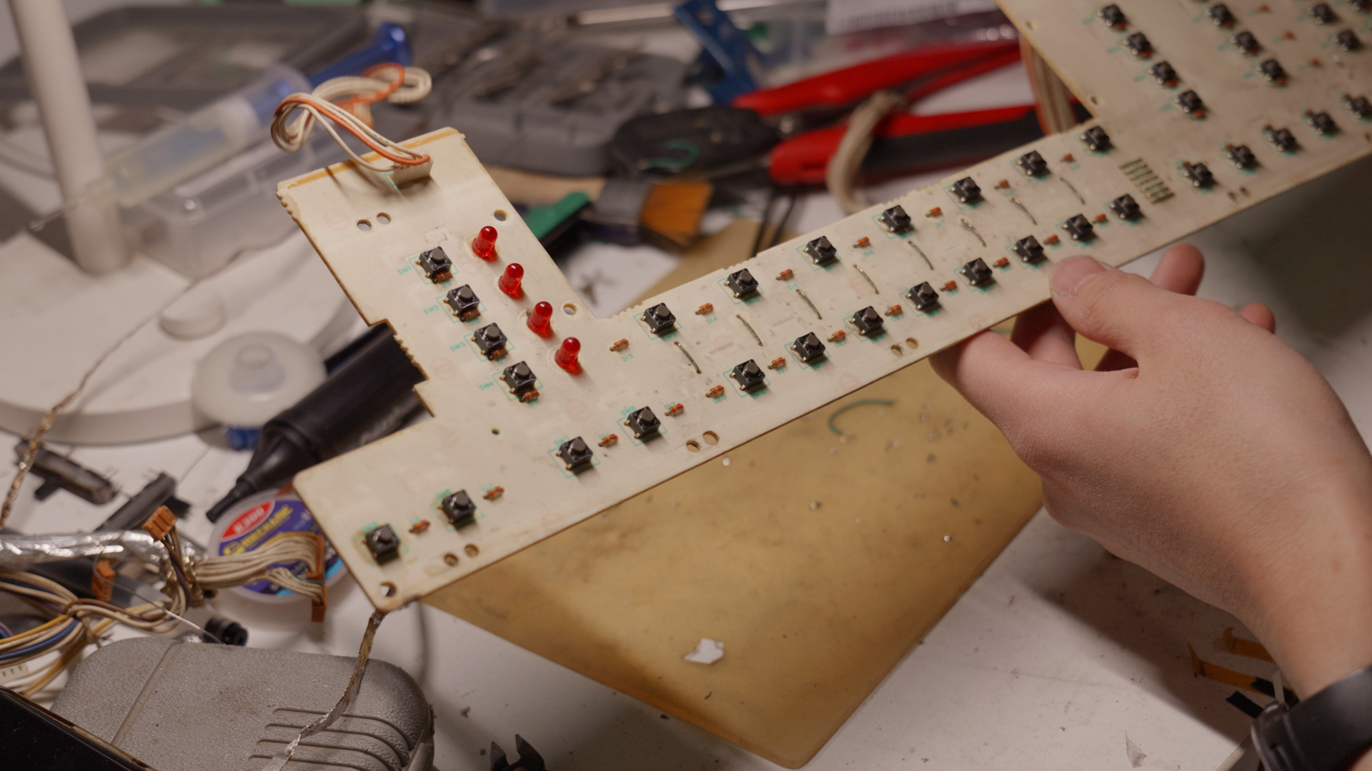
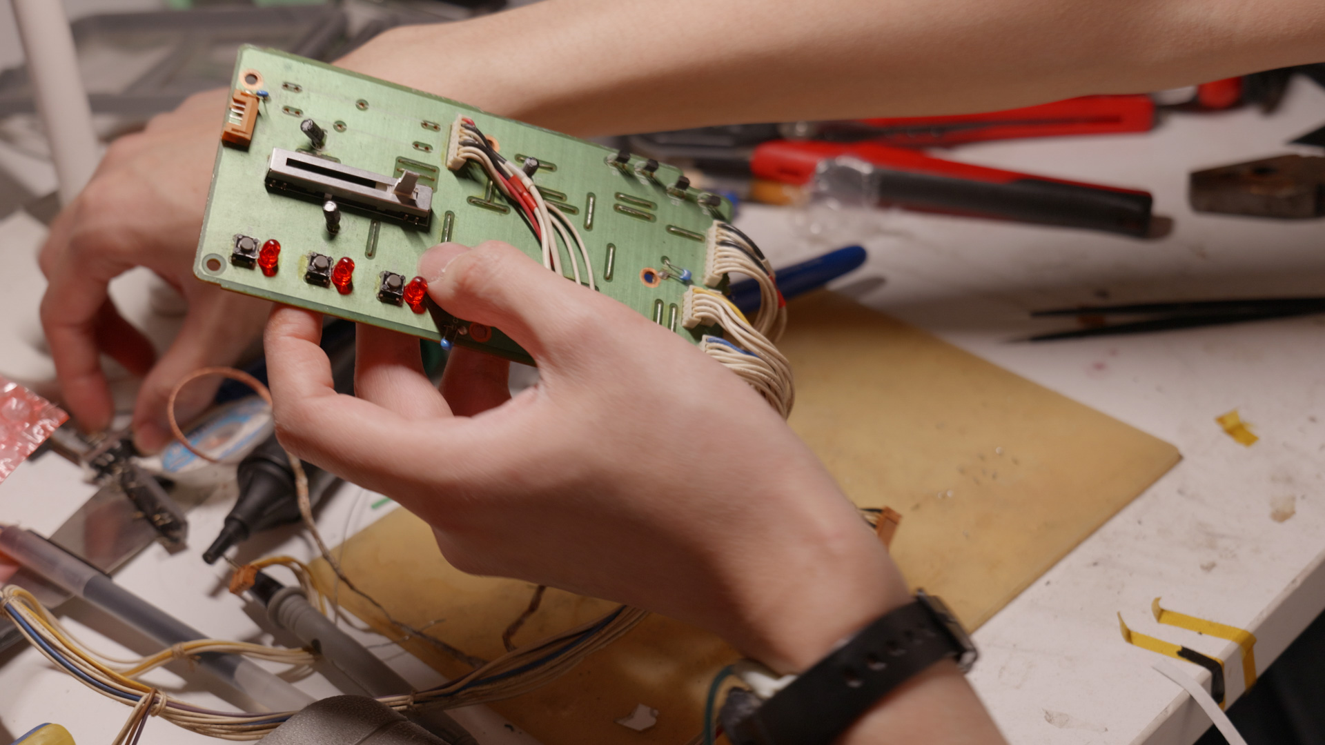
Panel Board
The panel boards contains the vast majority of the tactile keys and the display.
Changing the display
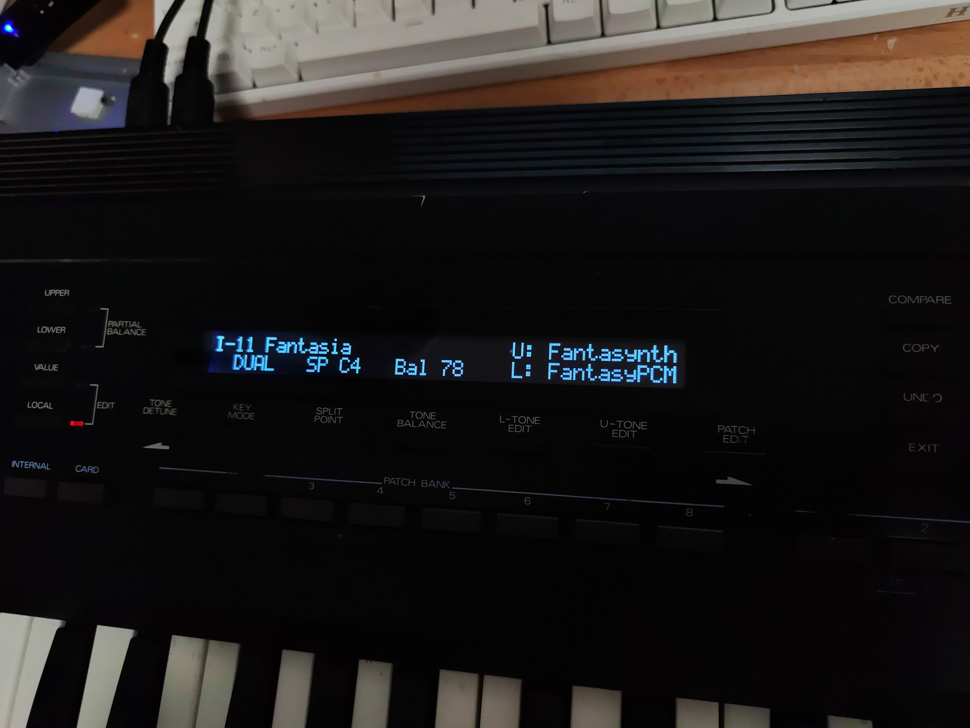
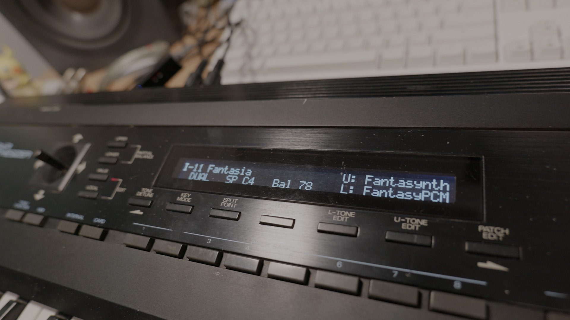
The LCD display uses a 40×2 standard module. The old one still works but the backlight is very faint. The backlight is soldered down to the LCD module PCB using a SMT fashion making it very hard to disassemble, and the PCB material is nothing like today’s fiberglass. It’s brittle. So I changed the module out with a modern 40×2 LCD, that has blueish white backlight which matches the D-50 logo well.
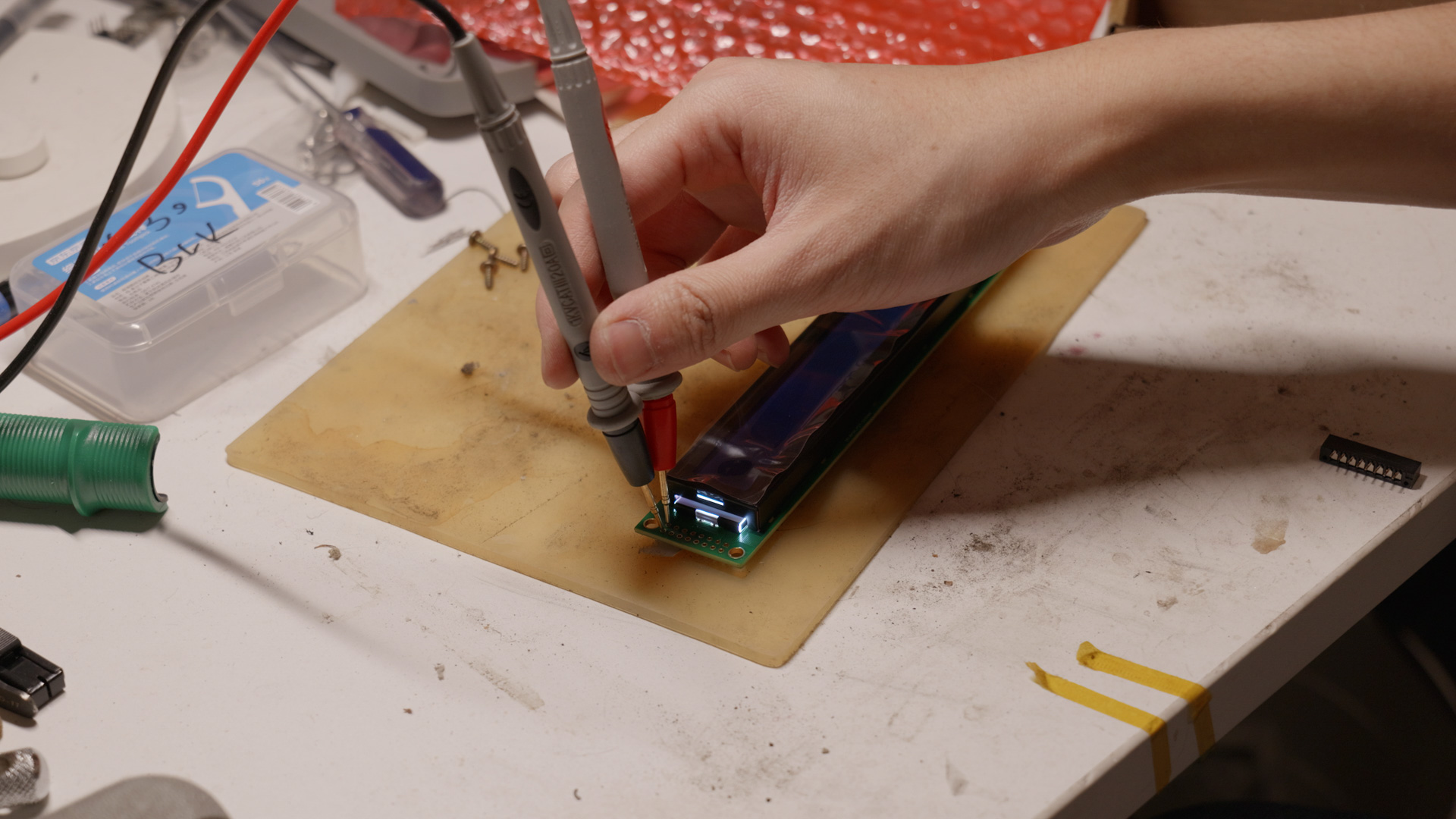
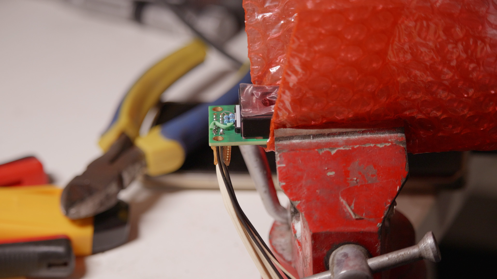
I ordered the display from a seller on Taobao (link here) and specifically asked for negative display in white (leave a note of “黑底白字” when placing the order and wait for the seller to modify the price). It cost CNY 46. After the module arrived I first tested the backlight and added a 16R resistor to power the backlight LED with 5V (their datasheet says 4.2V for the backlight).

Then I cut the cable from the old LCD module and soldered it onto the new module. The pinout is same as the original module, except the added 2 pin for backlight, which harvest power from pin 1 and 2.
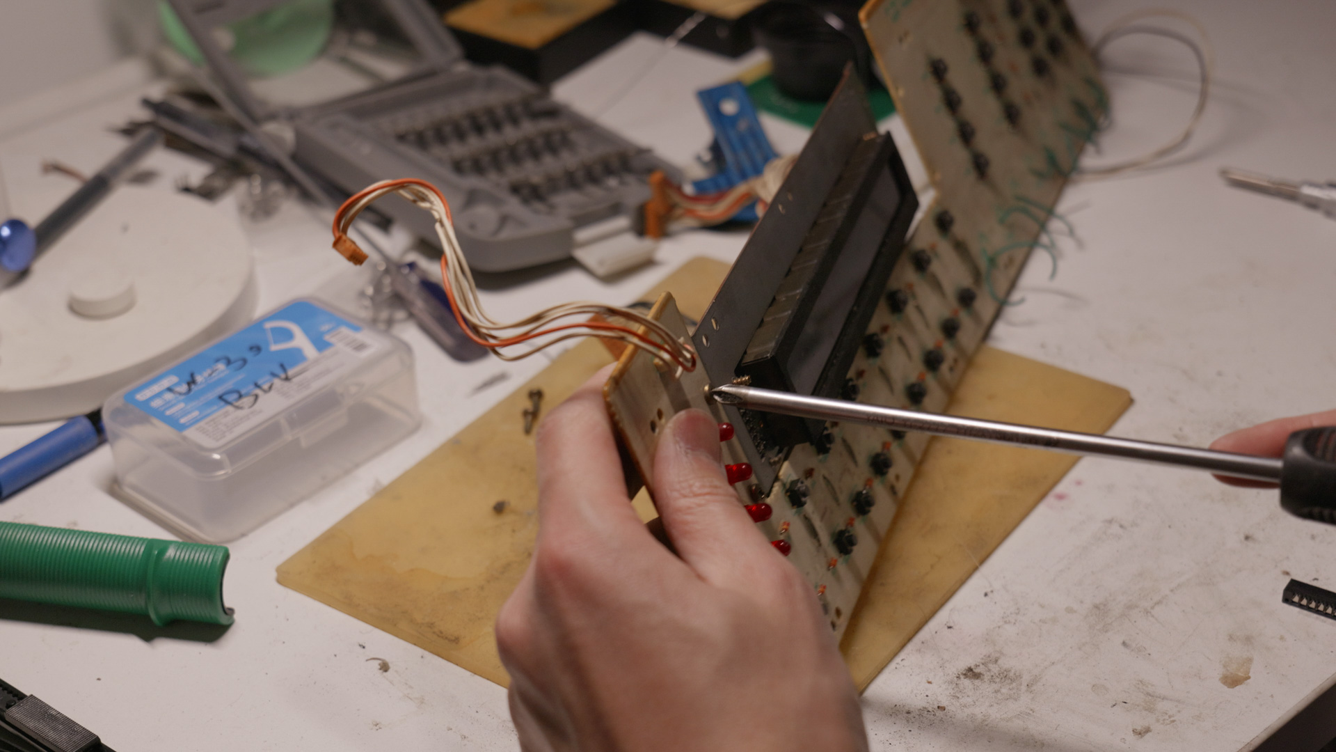
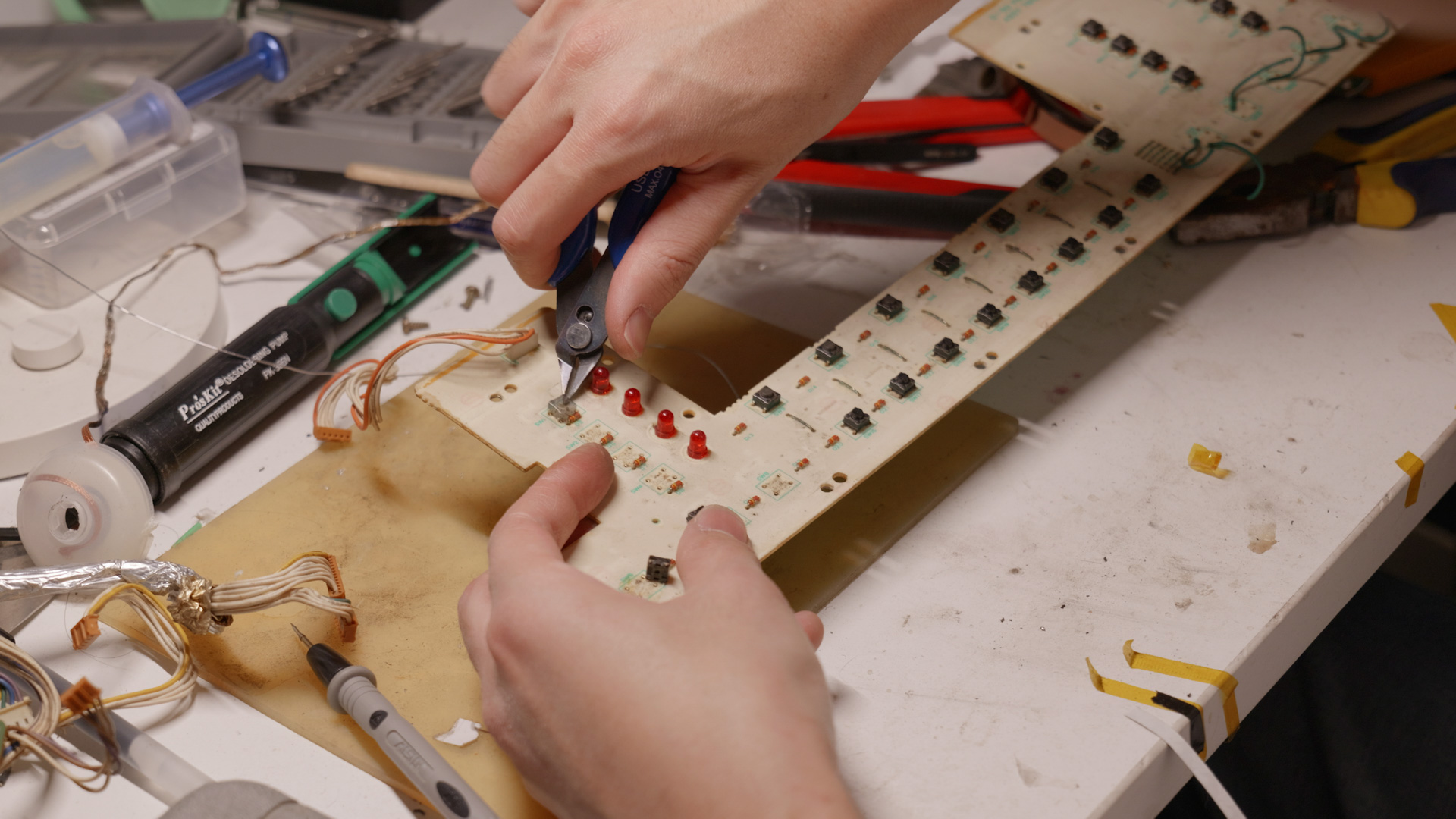
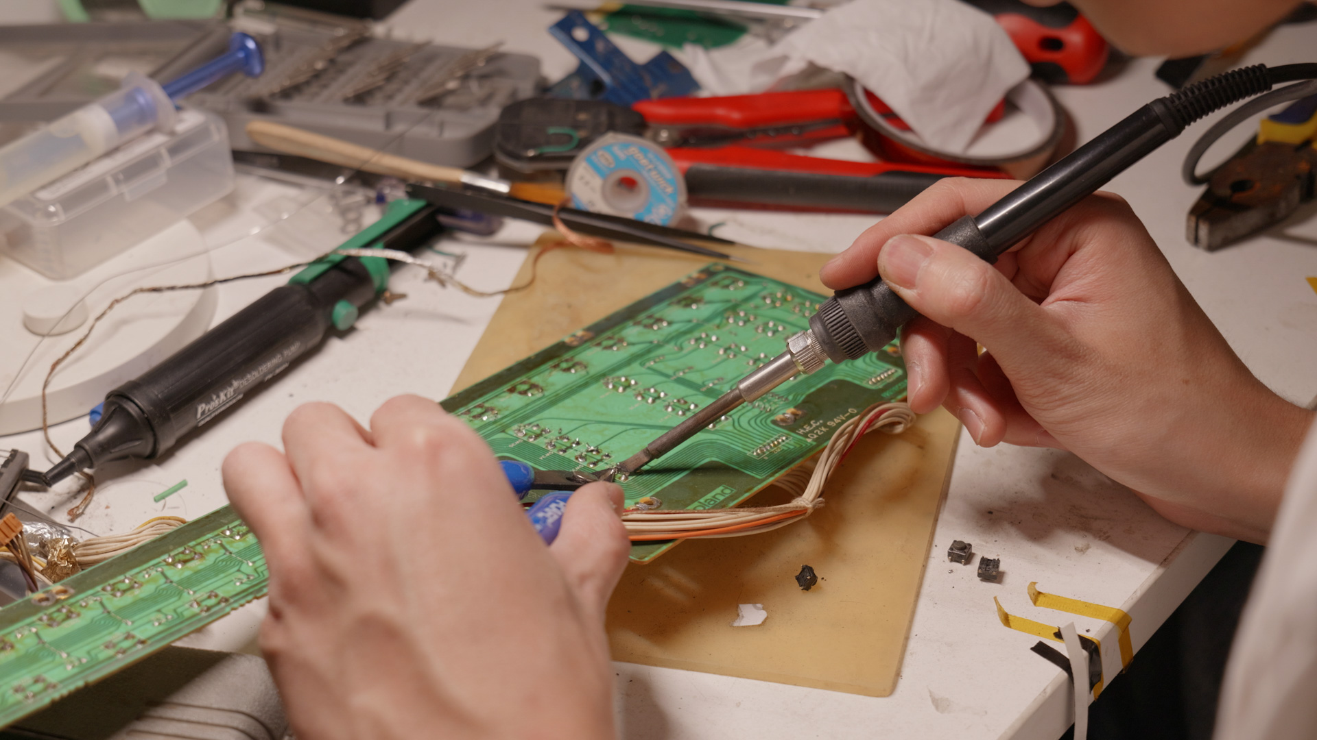
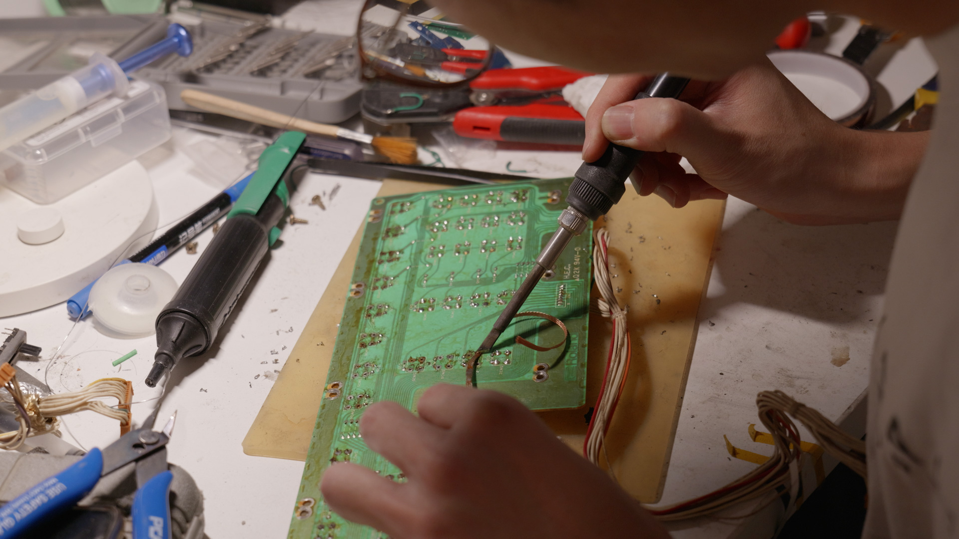
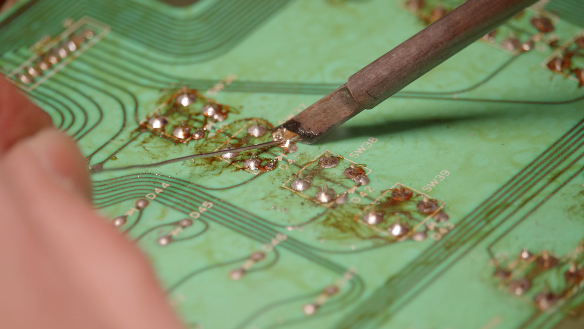
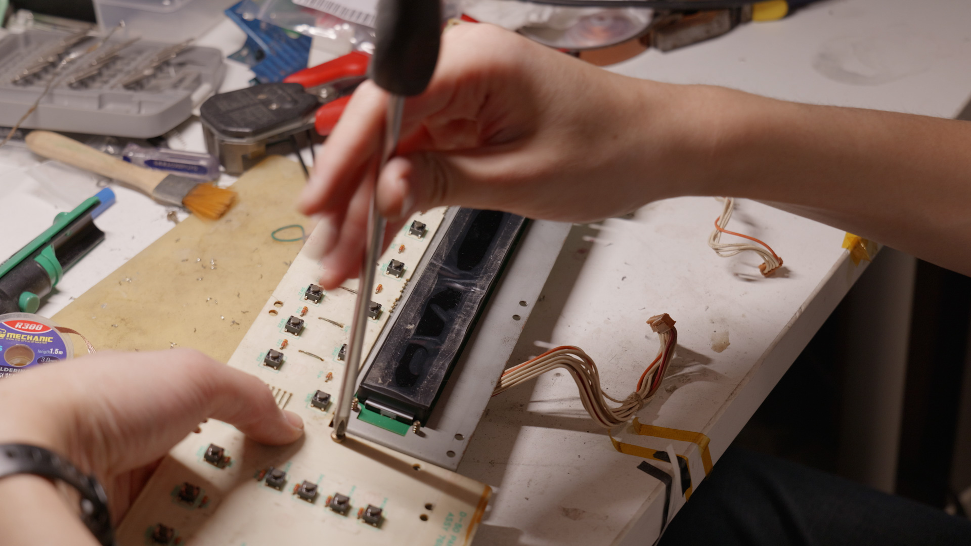
Replacing tactile switches
The next step is to replace all tactile switches since some has already gone bad. I ordered 60 pcs of SKHHAMA010 from LCSC. To remove the old switch I cut the pins with a wire cutter, then remove the pin from bottom side while heating the solder joint. This protects the PCB from overheating and pad lifts. After that I clean the pads with wick and install new switch.
After the switches were replaced, the panel board was reassembled.
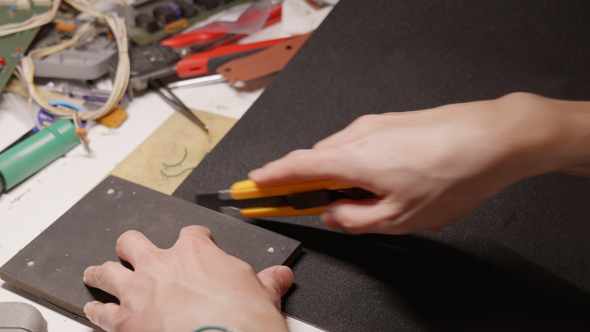
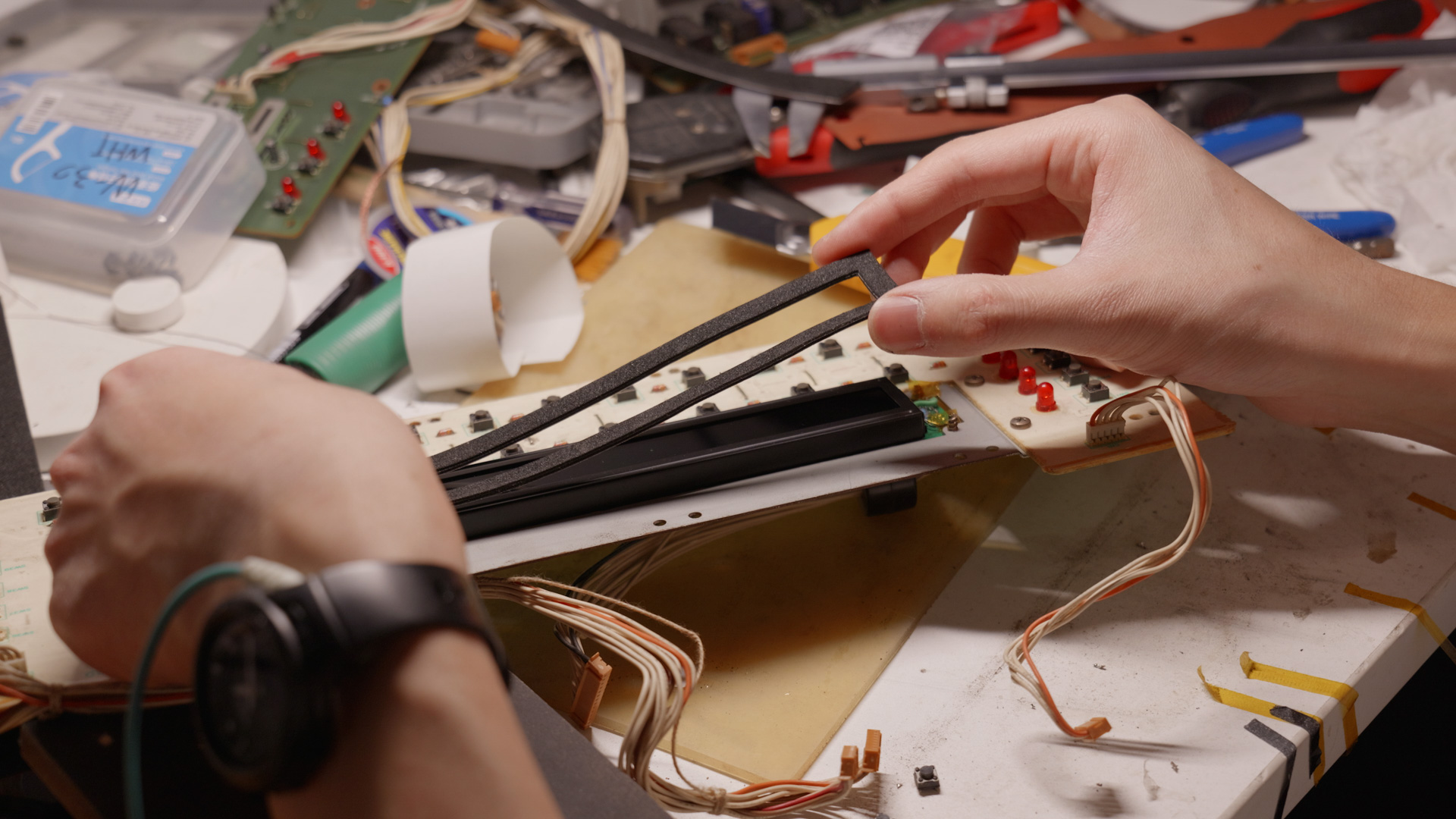
The LCD has a foam gasket which over the years has disintegrated. So I cut a new gasket with glue backed EVA foam.
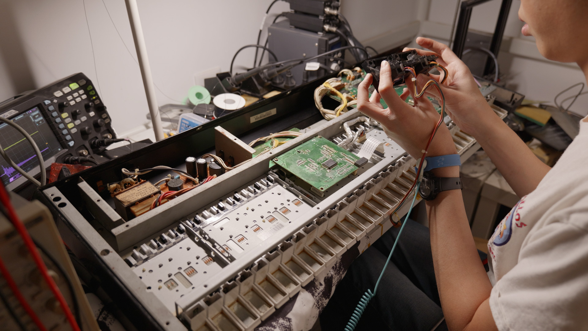
The Joystick
The two potentiometers on the joystick assembly works fine after a blast of contact cleaner. So I kept them and didn’t change those. I also used silicone lubricant on the mechanical parts of the joystick to make it move more smoothly.
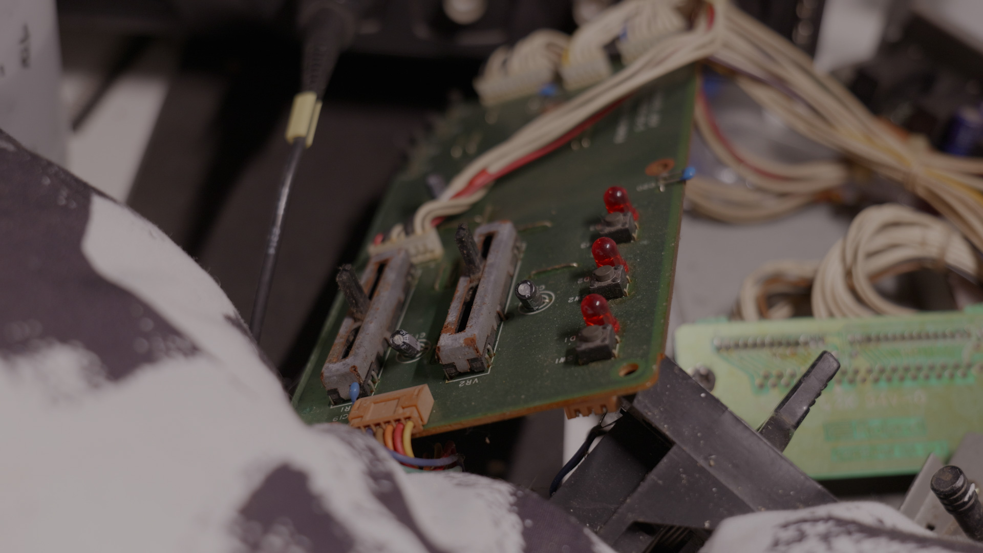
Bender Board
Potentiometer
I replaced the 2 potentiometers with new Panasonics ones. They have longer and thinner shaft so I had to cut those down and later install the knob with hot glue.
Aftertouch connector
Since I retained the W-30 keybed’s aftertouch board, it has a XH2.54 connector broken out. So I removed the connector on the bender board that connects directly to the after touch FPC, and put in a XH2.54 2 pin socket. This way I can use a XH to XH cable to connect the aftertouch to the bender board (to the right, the light purple cable).
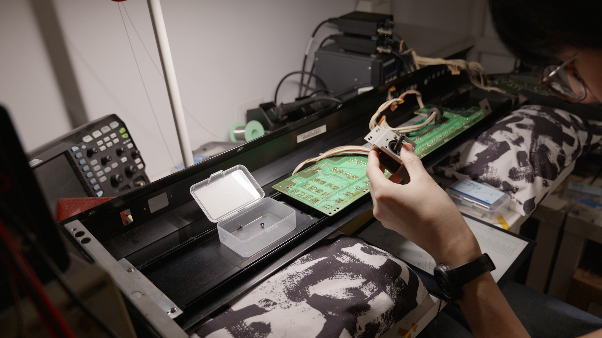
Bender Swap
The bender potentiometer is trashed. I tried to clean it with contact cleaner and is does not work at all. The modulation sensor also does not work. So I had to do a swap with the W-30 bender. Those two has identical frame and mechanism, only the bender handle is different. I removed the handle set screw with allen key, swapped the handle and installed the W-30 bender.
Power supply
I changed the 2-pin IEC C9 AC connector (https://en.wikipedia.org/wiki/IEC_60320) to a more common C13 socket. I also added the chassis ground connection to the PE terminal of the C13 socket.

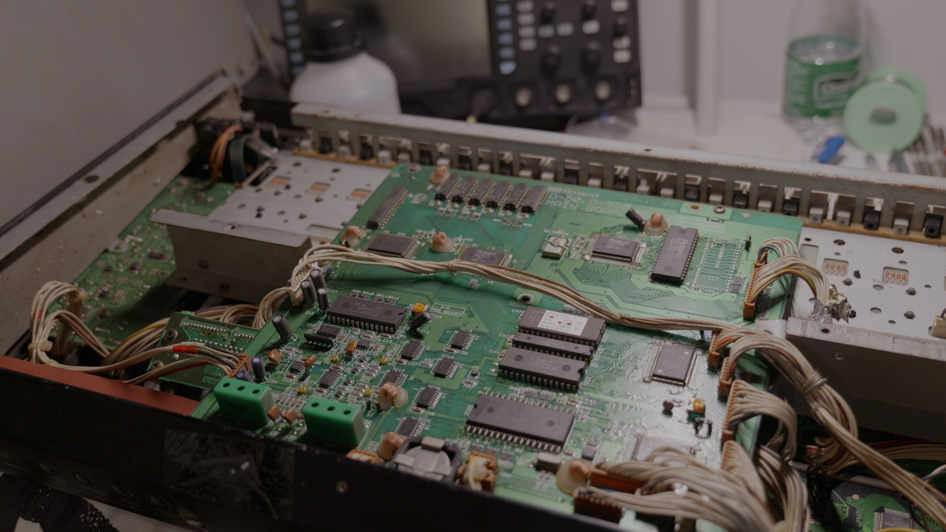
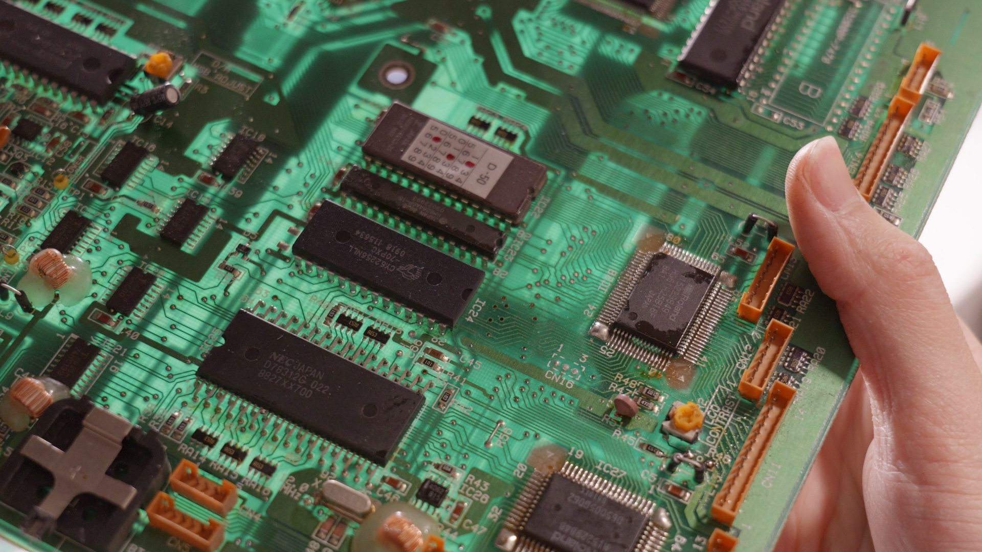
Main Board
After the above restoration I partly reassembled the machine, replaced the CR2032 battery and tested it. Everything works perfectly except the T-RAM problem. Patches in lower banks are corrupted along with system settings, and test mode shows T-RAM bank error or read write error.
I replaced the IC with a new 62256 from Cypress but it still does not work.
After tracing the lines, I found that pin 1 of IC24 does not connect to the corresponding pin (PQ6, pin 7) on CPU IC25 anymore. This is an address line of the SRAM, which explains why half of the RAM is not working.
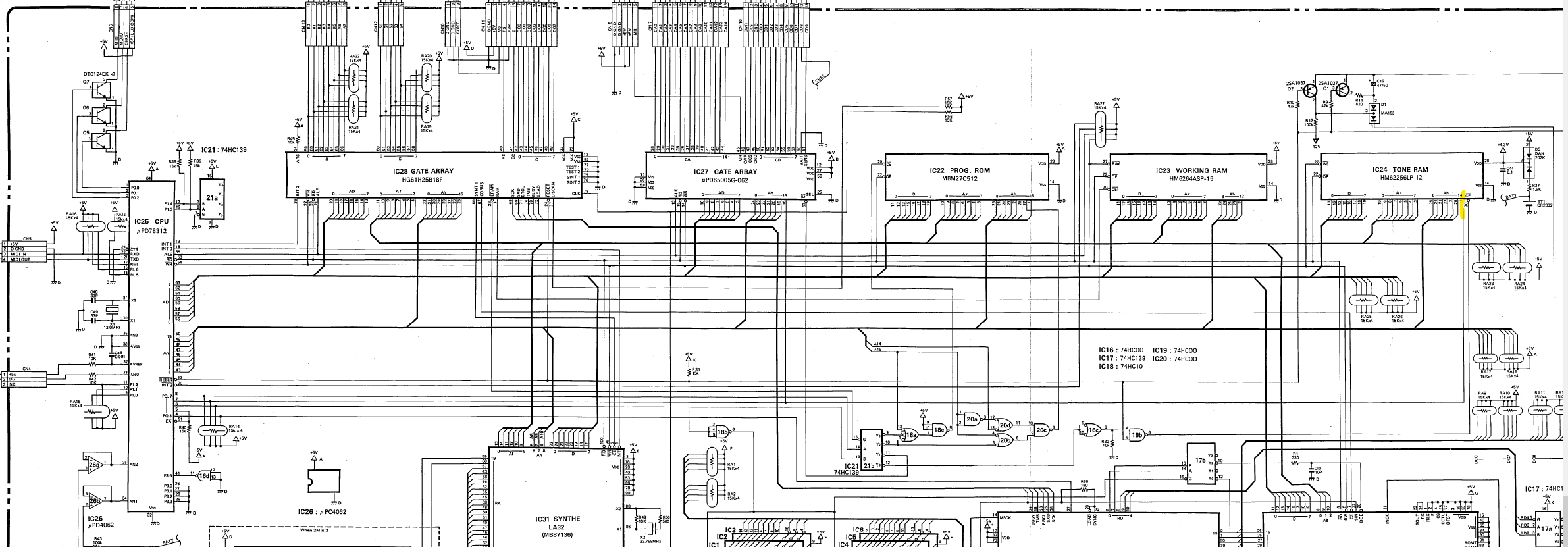
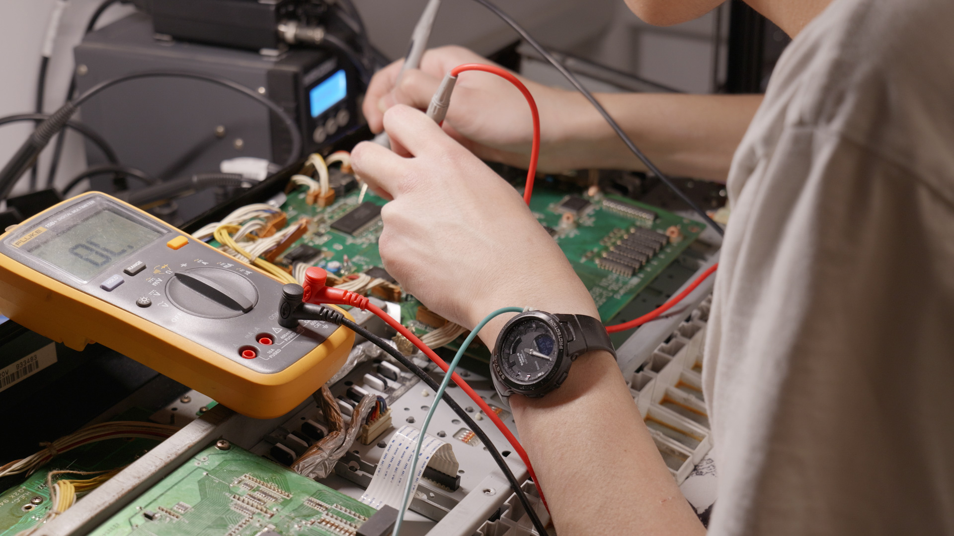
So I placed a airwire from pin 1 of IC24 to to pin 14 of IC27, which also belongs to the same network.
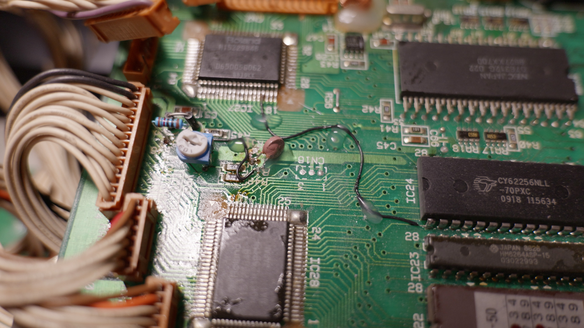
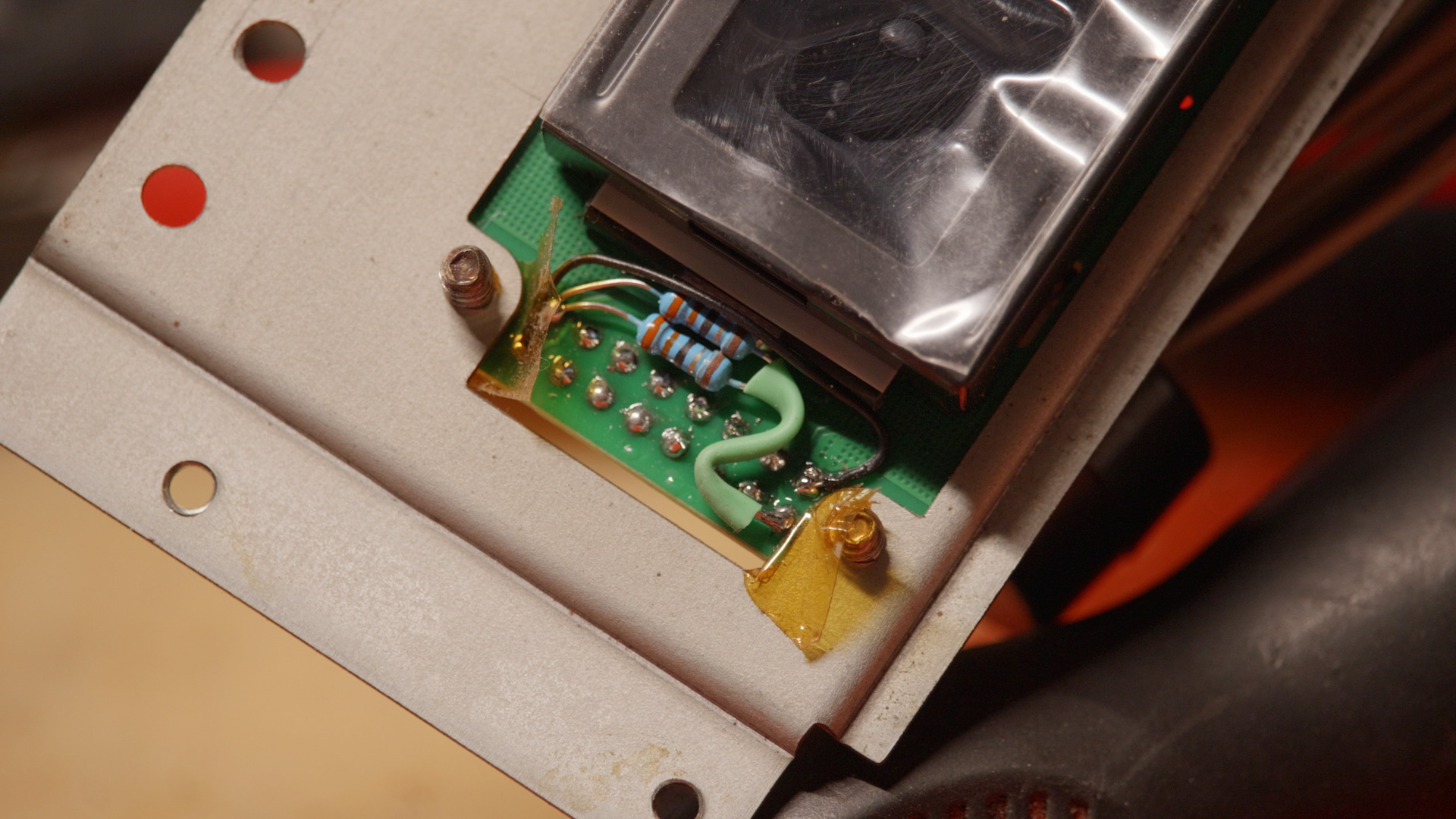
This turns out to be the fix needed. Also can be seen from the photo is the modification to the LCD contrast bias circuit. The original module uses negative bias, whereas the new module only requires bias near 0V or slightly negative. So I changed the resistor values to accommodate that. The brown component is the NTC resistor that provides temperature compensation of LCD contrast.
Final Assembly
Before reassemble everything, I re-flowed all SMT solder joints of QFP chips and all THT solder joints of DIP chips and connectors, with SnPb solder (non of those lead-free rubbish).
I applied new double sided tape to hold the buttons like other synths
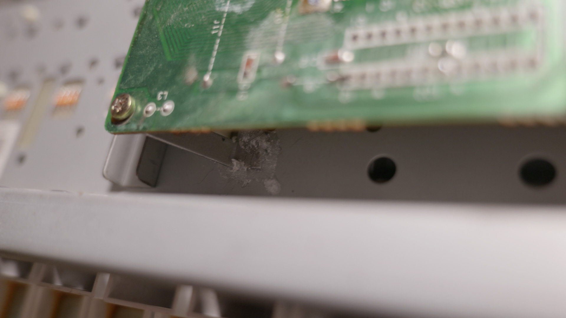
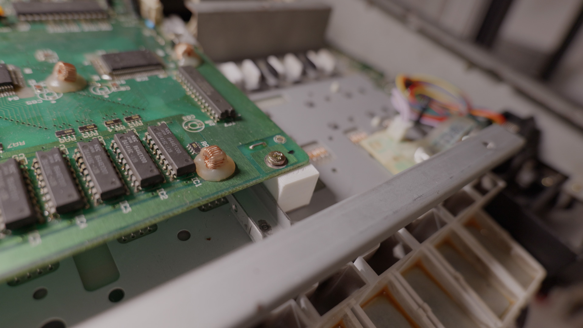
Board standoff is needed for the dynamic scan board and the main board. With the original keybed those were provided on the keybed frame. Since I used W-30 keybed I had to make my own board standoff.
To protect the potentiometers I also added EVA foam to the potentiometer openings.
After bundling the wires and fastening all the screws, this repair is completed. There is nothing short of D-50 demos on the internet so I don’t think it’s necessary to post any more. I’m glad that I kept the W-30 for all this time. I hope you enjoyed this repair writeup. Thank you for reading this post.
Nice job. I am buying a pretty busted up Roland D50, so this is amazingly helpful.
Do you thing the blue logo is obtainable? As it is pretty battered on the one I am getting.
Thank you 🙏
Thank you for your comment. For the logo unfortunately I don’t think so. You should get in touch with a local artist who can print/draw the logo.