Table of Contents
- Summary
- Sampling
- Bandwidth
- Waveform Interpolation
- References
Summary
This is the first publish of this series where I present some aspects that distort electrical signal measurement result. In this article I will focus on artifacts introduced by improper oscilloscope parameter selection and settings related to sampling. This one focus on what happens in the scope itself after the signal has entered an oscilloscope.
Sampling
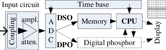
Digital real-time oscilloscopes create representation of waveform by sampling the signal using an ADC. This is not an ideal process. The signal goes through conditioning circuit, sampled by ADC, processed by DSP and finally displayed.
The higher the sample rate vs the signal bandwidth, the more fidelity there is to recreate the signal. According to sampling theory, you need a sample rate at least 2 times the signal bandwidth.
Bandwidth
System bandwidth, including those of the oscilloscope, the probe, and any other component that may be involved, is an important parameter to consider. Usually, we choose a bandwidth according to the bandwidth or edge rate of the signal. For example, measuring a GPIO would usually call for a modest bandwidth of 500MHz or less.
When selecting the bandwidth, we should consider the edge rate, that is the rise or fall time of the signal. In general, we should opt to have a system bandwidth that is at least as large as the signal bandwidth using a Gaussian approximation for the input filtration stage for the scope.
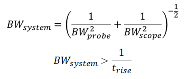
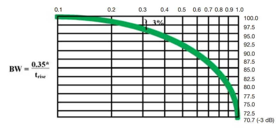
Here, we’ve set the low-pass bandwidth to the inverse of the rise time for the digital signal we want to measure, which will provide plenty of headroom for our measurement. Note that, for a first-order filter, the signal bandwidth is 0.35 divided by the rise time (so-called knee frequency), but higher-order filters will have different values in the numerator. The typical rule of thumb is that our oscilloscope bandwidth should be double the signal bandwidth for the given filter order on our oscilloscope front-end, but setting the numerator to 1 provides about 3x bandwidth.
Key Point: When calculating the required bandwidth, using 1 to divide the rise time. This gives enough bandwidth margin in almost every case.
Bandwidth and Sample Rate in Digital Oscilloscopes
The analog front-end in digital oscilloscopes are modelled as a high-order low pass filter. It will have a cut-off frequency near the stated bandwidth of that oscilloscope. When you are using the maximum sample rate the scope can offer, the sample rate is usually 2 to 10 or more times the bandwidth, providing sufficient sample points.
However, as the sample rate is turned down either manually or automatically by the scope due to long acquisition, the sample rate may no longer be enough for the signal bandwidth that is entering the ADC.
Most scope automatically reduce sample rate when acquisition time is longer because 1) the scope has limited waveform memory, if it don’t do so the waveform cannot fill the whole screen, 2) the scope UI may become too laggy with too large a number of sample points.
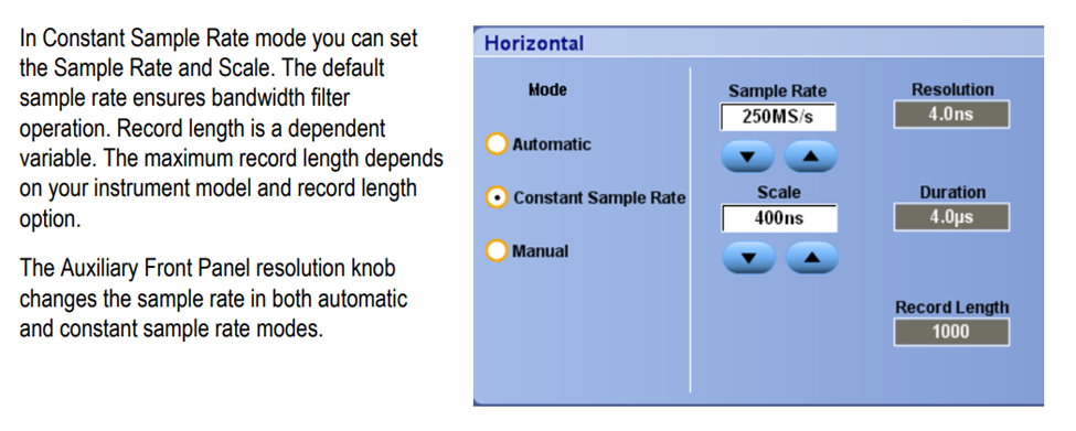
It’s important to ensure we have a high enough sample rate. By default scopes automatically set their memory depth and sample rate. For long acquisition we may want to use constant sample rate mode or manual mode to set the sample rate accordingly.
Aliasing
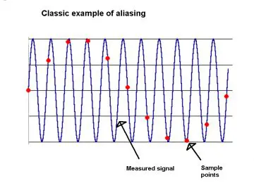
Another problem that arise when sample rate is low and signal bandwidth is high, is aliasing. You have seen in TV where the helicopter rotor seems to be spinning very slow or does rotate at all, and fans and car wheels spinning backwards. That’s the same principle.
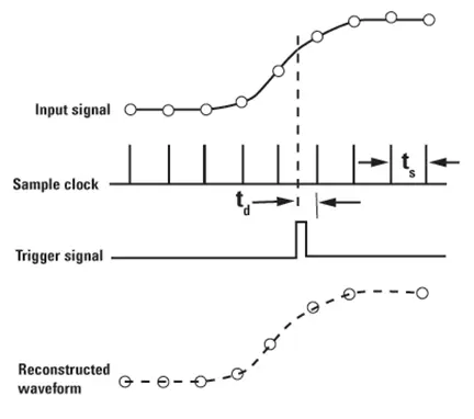
There are 2 types of aliasing, sampling aliasing and display aliasing. As the photo shown above, sample aliasing happens when a periodic signal with high bandwidth is acquired with a low sample rate, and an inaccurate representation of the waveform is seen by the ADC. The reason is same, signal frequency higher than what the ADC is capable of has entered the ADC.
Another form of aliasing is display aliasing, where a poorly designed display algorithm extracts sample points from the sample memory, and again a periodic sampling of higher frequency signal occurs, only this time it’s a signal in the memory.
Generally aliasing is a bad thing, but some times it may give another perspective of the signal, like frequency or phase shift.
Key Point: Ensure the actual sample rate is high enough for the signal being observed. Manually set sample rate when necessary.
Waveform Interpolation
Gibbs Ringing
Gibbs Phenomenon, or Gibbs ringing, refers to the ringing after either rising or falling edge caused by a lack of high frequency content. According to Fourier transformation, we know that any signal can be broken down to combinations of sine waves of different frequency, phase, and amplitude.
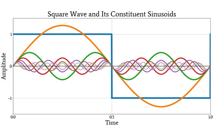
A square wave or similarly a fast edge contains a lot of harmonics. When the high frequency content is eliminated, ringing starts to appear.
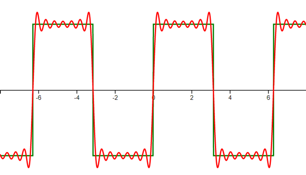
Example of ringing on the leading and falling edges of a square wave pulse train calculated up to 7th order with a Fourier series. https://resources.altium.com/p/how-gibbs-phenomenon-produces-measurement-artifacts
As high frequency energy is attenuated, the sharpness(where transition is fast, hence high frequency components) is lost. This is called the Gibbs Phenomenon or Gibbs ringing. It refers to the ringing before/after either rising or falling edge caused by a lack of high frequency content.
Note that Gibbs phenomenon is non-casual, means it won’t appear directly in real physical systems. But this does not mean it won’t set us back in other ways.
Waveform Interpolation
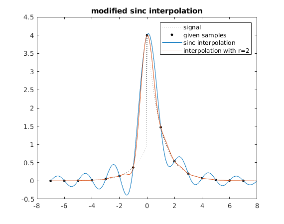
Oscilloscopes incorporate data interpolation to connect and smooth out data points acquired from the front end ADC. Apart from joining the dots with straight line (linear interpolation), sin(x)/x or sinc is often used as it can smooth out signals, create accurate waveform and reduce requirement on bandwidth.
sinc (sinx/x) Interpolation
Apart from joining the dots with straight line (linear interpolation), sin(x)/x is often used as it can smooth out signals, create accurate waveform and reduce requirement on bandwidth.
Most scopes, when using full sample rate, can safely use sin(x)/x interpolation, as their analog front ends are designed to operate at the maximum bandwidth suitable for full sample rate, and will cut off any frequency content that’s too high. Unfortunately again when sample rate is not at the maximum, unless hardware analog front end bandwidth limit is enabled, signals that have a frequency higher than what the ADC can acquire will enter the ADC.
Here is why “Gibbs Ringing is non casual”: if use linear interpolation, just connect sample points with line, you at worst get an inaccurate representation of the actual waveform. However with sinc interpolation such situation may cause additional ringing.
Ringing Caused by sinc or sinx/x Interpolation
So high frequency signal enters ADC. In a less than ideal situation, at the digital signal domain, the edge swings too fast, let’s say within 2 to 3 sample points. When you apply sin(x)/x interpolation on such signal, Gibb Ringing will occur.
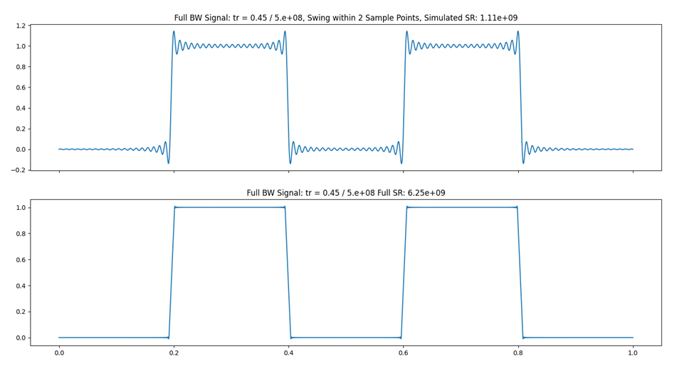
Simulation of sinc interpolation with too low sample rate
The following image is a simulation of this with python, in this example we simulate a signal that has an equivalent edge bandwidth of 500MHz (9 ns, using 0.45 factor), into a 6.25GSa/s (more than enough bandwidth) scope. It was also simulated under a lower sample rate (top figure) where the edge transit within 2 sample points. Sinc interpolation algorithm from https://gist.github.com/endolith/1297227 was applied to both signals. The ringing can be clearly observed.
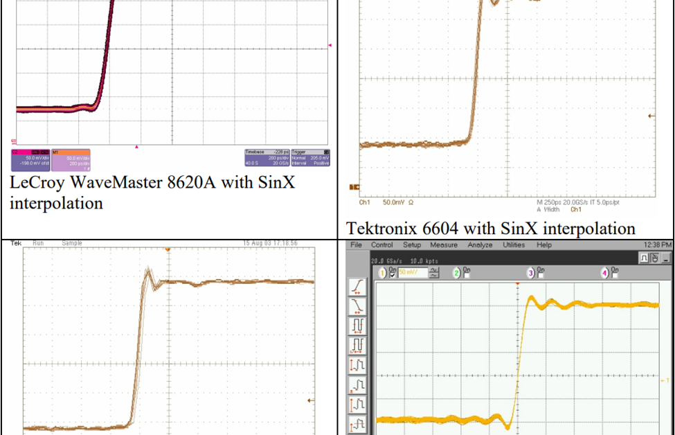
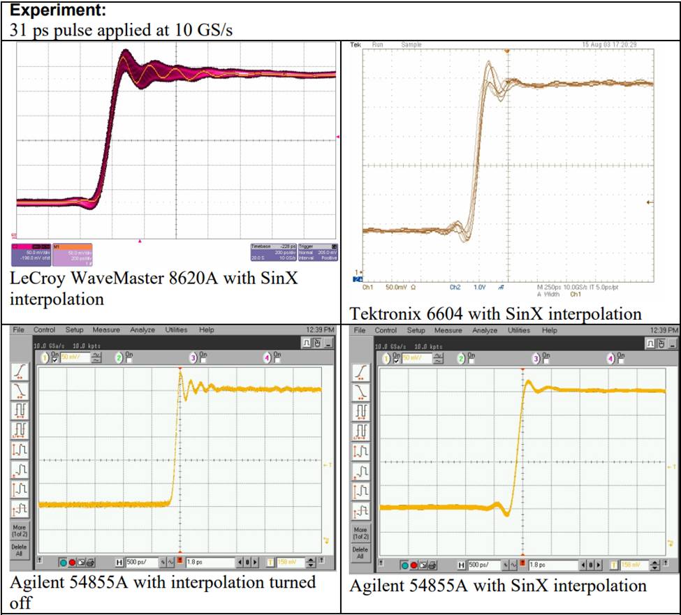
Experiment using real scopes to try interpolation at not enough sample rate (below Nyquist)
Similar experiments have also been done by oscilloscope vendors. The following experiment done by LeCroy uses a 31ps rise time pulse. Using the .35 factor we can estimate an equivalent bandwidth of about 11.3GHz. 4 different DSOs were used, they were the LeCroy Wavemaster 8620A, Tektronix 6604, and Agilent 54855A. All three oscilloscopes have a 6 GHz bandwidth specification and a maximum sample rate of 20 GS/s. Signal was acquired at 20GSa/s (above Nyquist) and 10GSa/s (below Nyquist) with each DUT.
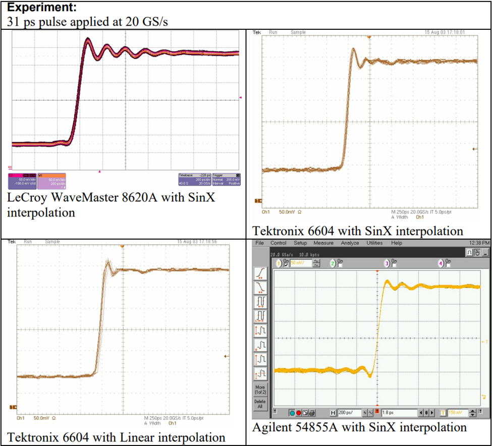
As sample rate decrease, the analog front end will still feed full bandwidth signal into the ADC, this is when interpolation error will occur.
Sinc interpolation error in real measurement
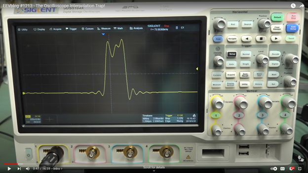
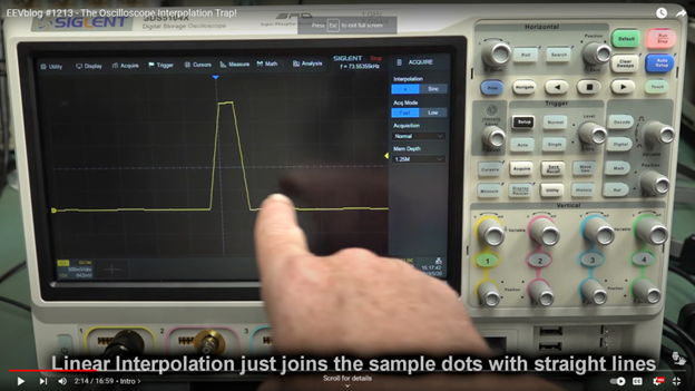
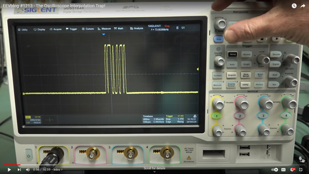
This following EEVBlog video discussed the possible measurement deviation caused by sinc interpolation. The leftmost photo, shot at 2ns/div, 2.5MSa/s, shows a somewhat valid signal. But on further calculation, we only have 5 sample points per every 4 div. With sinc interpolation on, this caused a huge ringing error. The center photo shows the same signal but the display is using linear interpolation. Finally the rightmost photo revealed what the signal actually is by using a high enough sample rate.
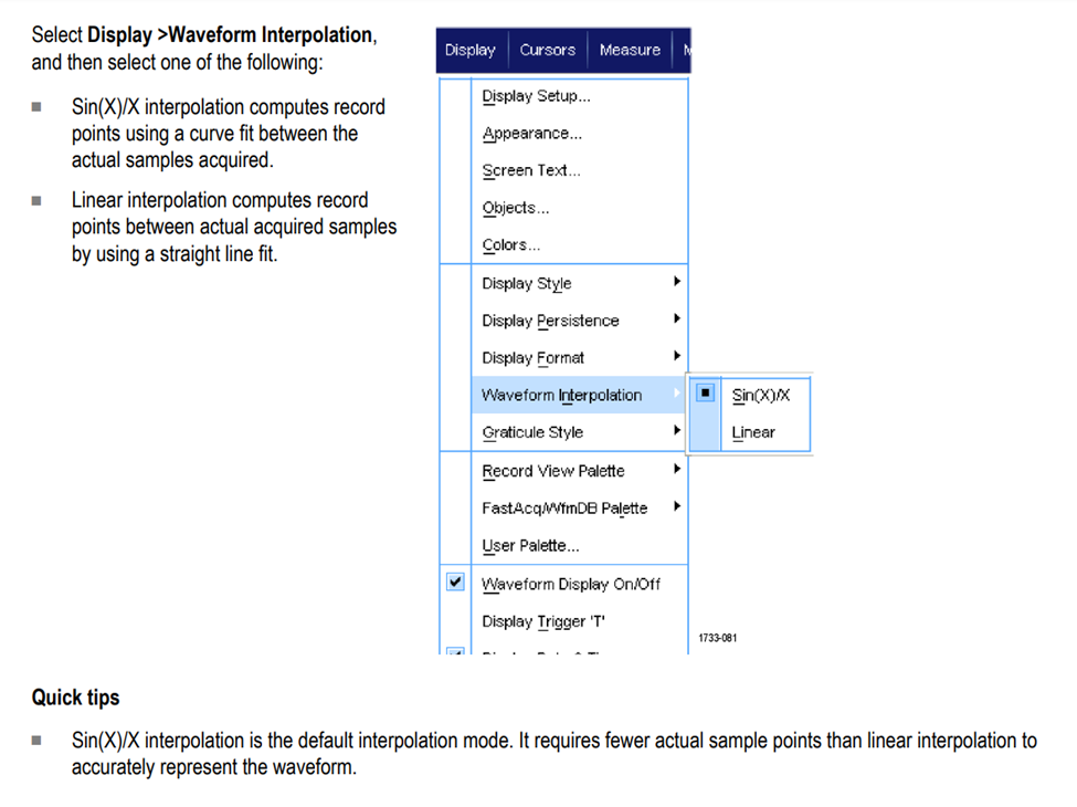
Be careful when you see ringing, especially those looks too perfect to be actually in the signal. Always check if sample rate is not enough while sinc interpolation is still on. For scopes that does not automatically turn off sin(x)/x interpolation, we should turn it off manually when sample rate is too low. This can usually be set in the display menu:
Key Point: When sample rate is low and ringing is present, see if sinc interpolation is causing added error.
References
- https://people.ece.ubc.ca/robertor/Links_files/Files/TEK-Understanding-Scope-BW-tr-Fidelity.pdf
- https://resources.altium.com/p/how-gibbs-phenomenon-produces-measurement-artifacts
- https://www.tmatlantic.com/encyclopedia/index.php?ELEMENT_ID=10969
- https://download.tek.com/manual/DPO70000SX-Series-Real-Time-Oscilloscopes-User-Manual-EN-071335707.pdf
- https://gist.github.com/endolith/1297227
- https://cdn.teledynelecroy.com/files/whitepapers/wp_interpolation_102203.pdf
- https://www.youtube.com/watch?v=W4twnd-YQQ4
- https://www.signalintegrityjournal.com/articles/2175-how-to-avoid-gibbs-ringing-artifacts-in-measurements