Check out my repair video on BiliBili (some demos in part 3):
And a cover of Never Gonna Give You Up:
Never Gonna Give You Up on XP-80
Table of Contents
- First Impression
- Testing the Power Rails
- Replacing All Electrolytic Capacitors
- More diagnosing
- Luck Strikes
- More Problem
- Improve with a USB Floppy Emulator
- Thoughts and Notes

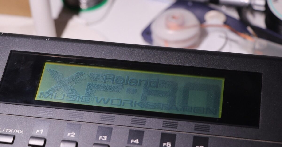
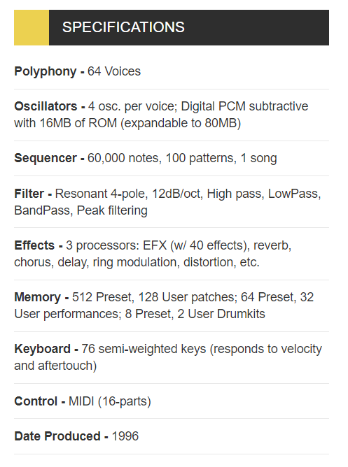
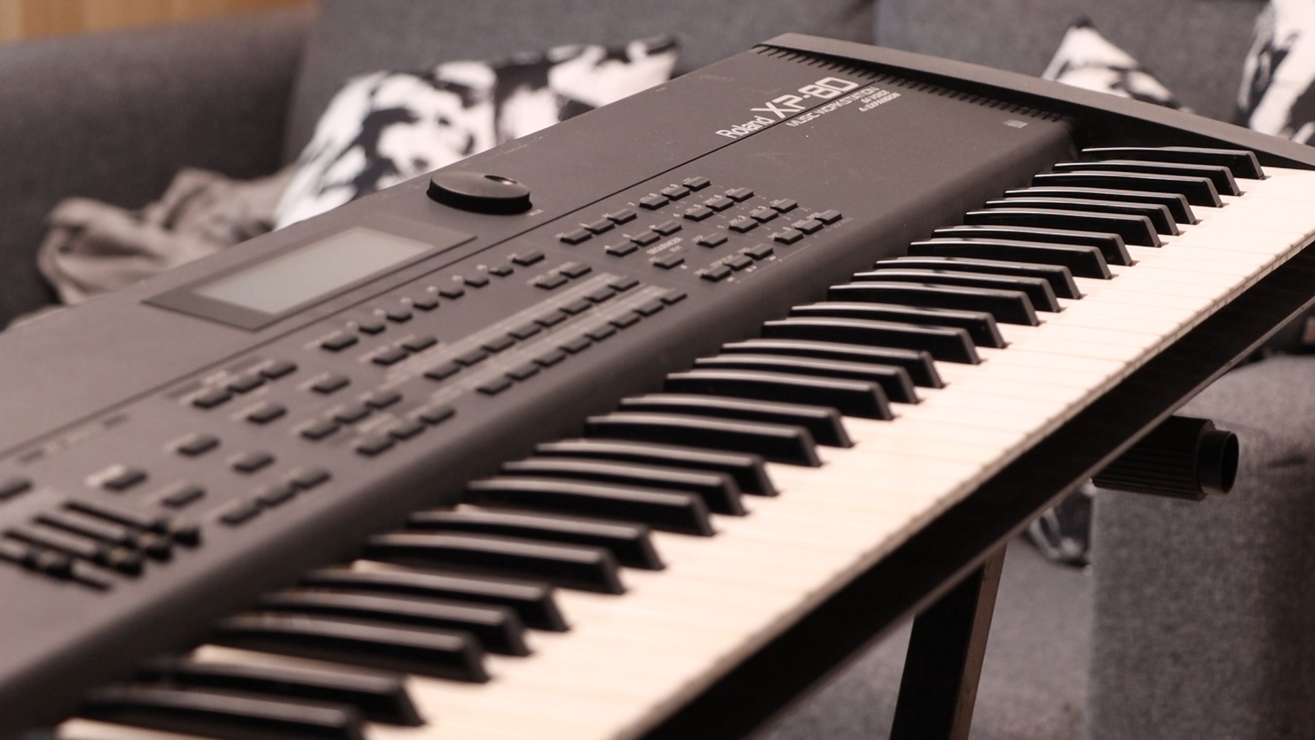
The Roland XP-80 is a flagship synthesizer / music workstation released in the 1990s. Featuring 64 concurrent voices and a maximum 40MB of waveform memory when fully extended, this synth is a powerhouse.
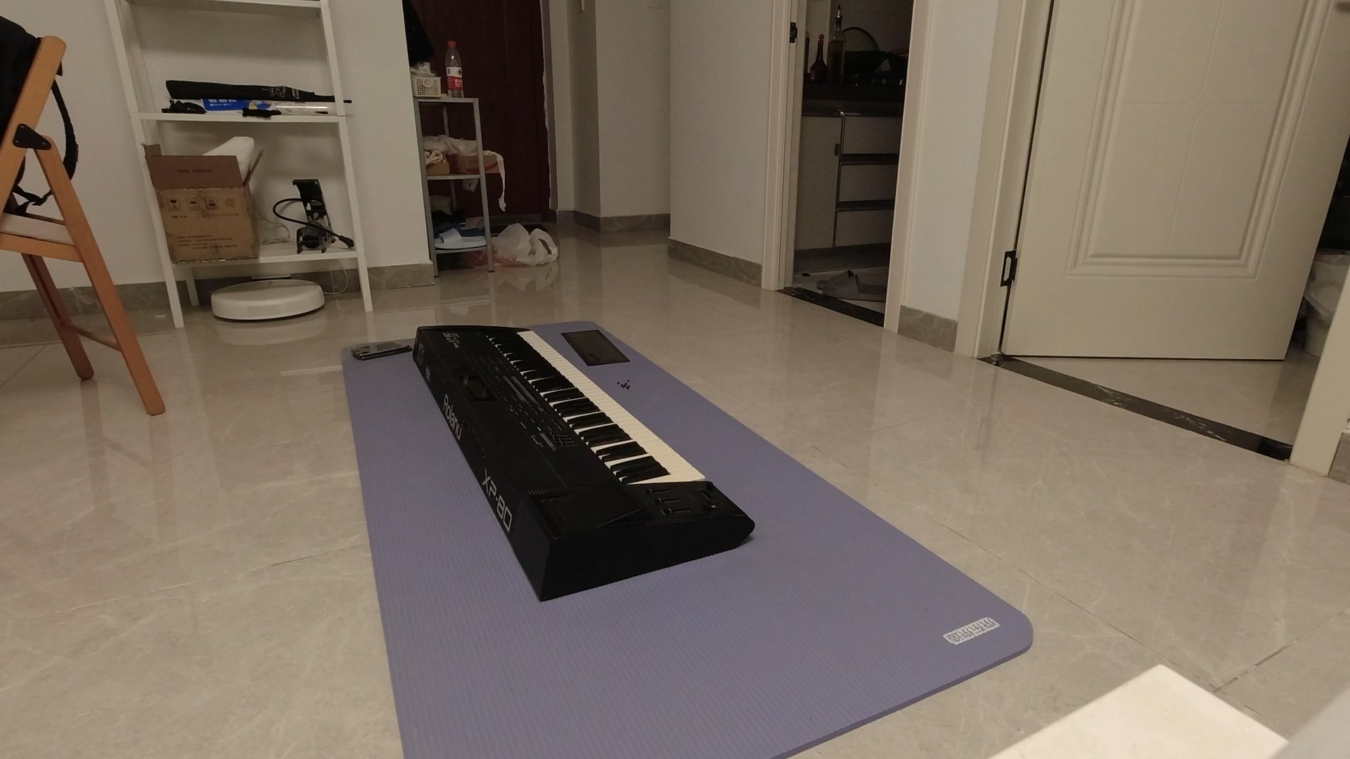
I acquired a non-working XP-80 in August, 2021. I bought it for CN¥800 (about US$150), and it was in overall great condition.

By the way this synth weights a ton. A quick measure on the body weight scale showed more than 13kg (nearly 30lbs).
First Impression
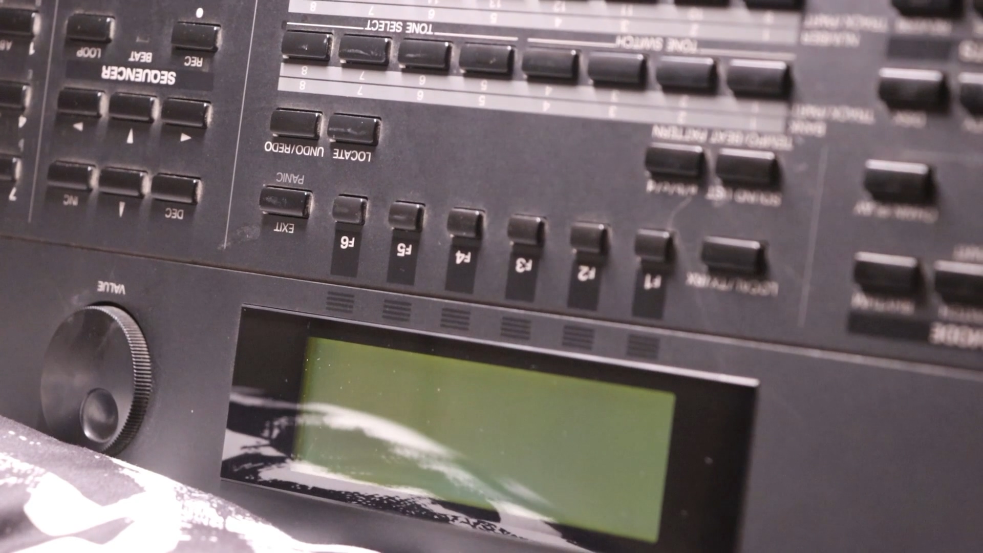
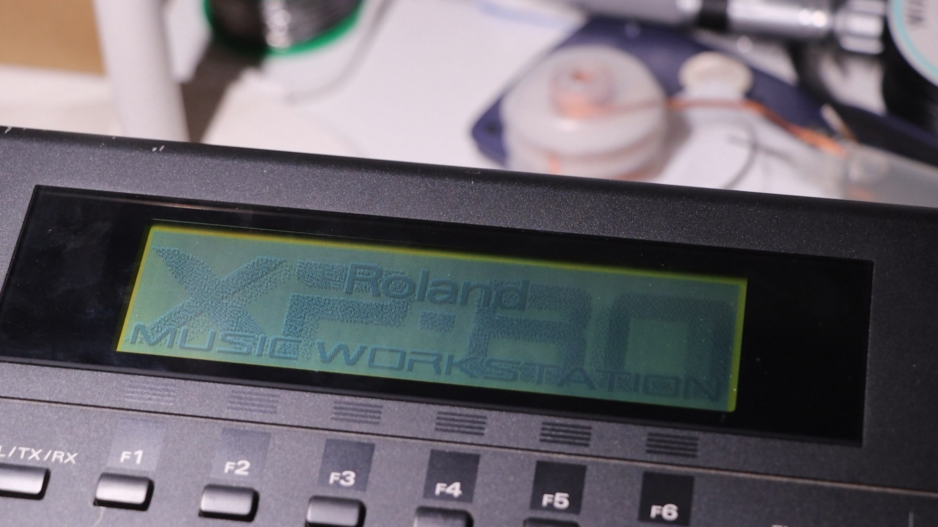
The unit is a 110V unit rewired for 220V operation. A quick test shows that the machine cannot boot, and the LCD screen flickers with lines on it. Some LEDs would light up, which I and some other believes are error code. But the service manual said nothing about it and without the embedded software source code it’s impossible to know what it means.
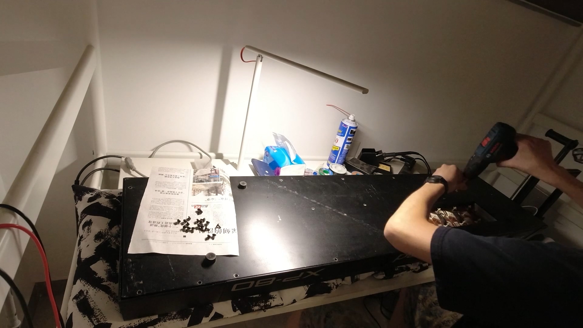
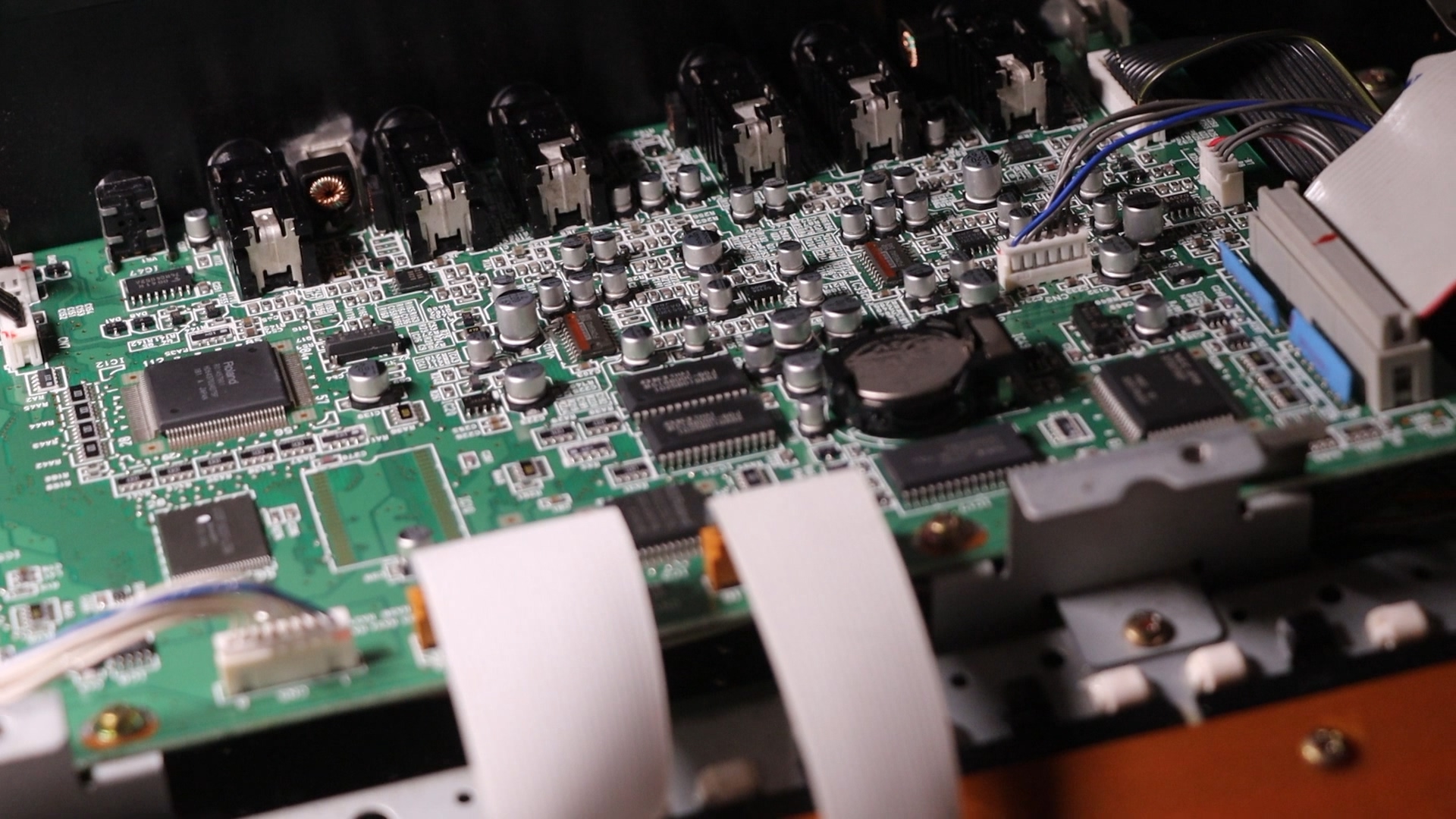
I put some cheap pillows from IKEA between the synth and the desk to cushion it. After tearing it down first thing I noticed is the dead CR2032 battery. I replaced the battery with a new one, and it still won’t boot.
Testing the Power Rails
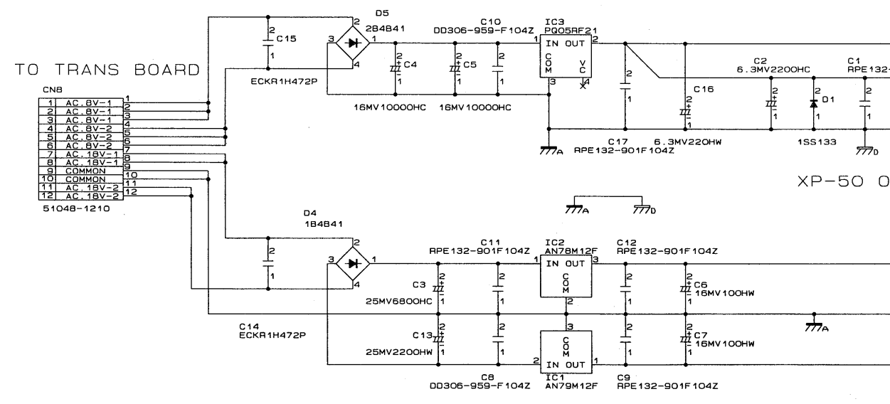
Since the most common problem around this machine is power supply issue caused by dried out capacitors, I tested the supply rails with DMM and oscilloscope, everything checked out fine.
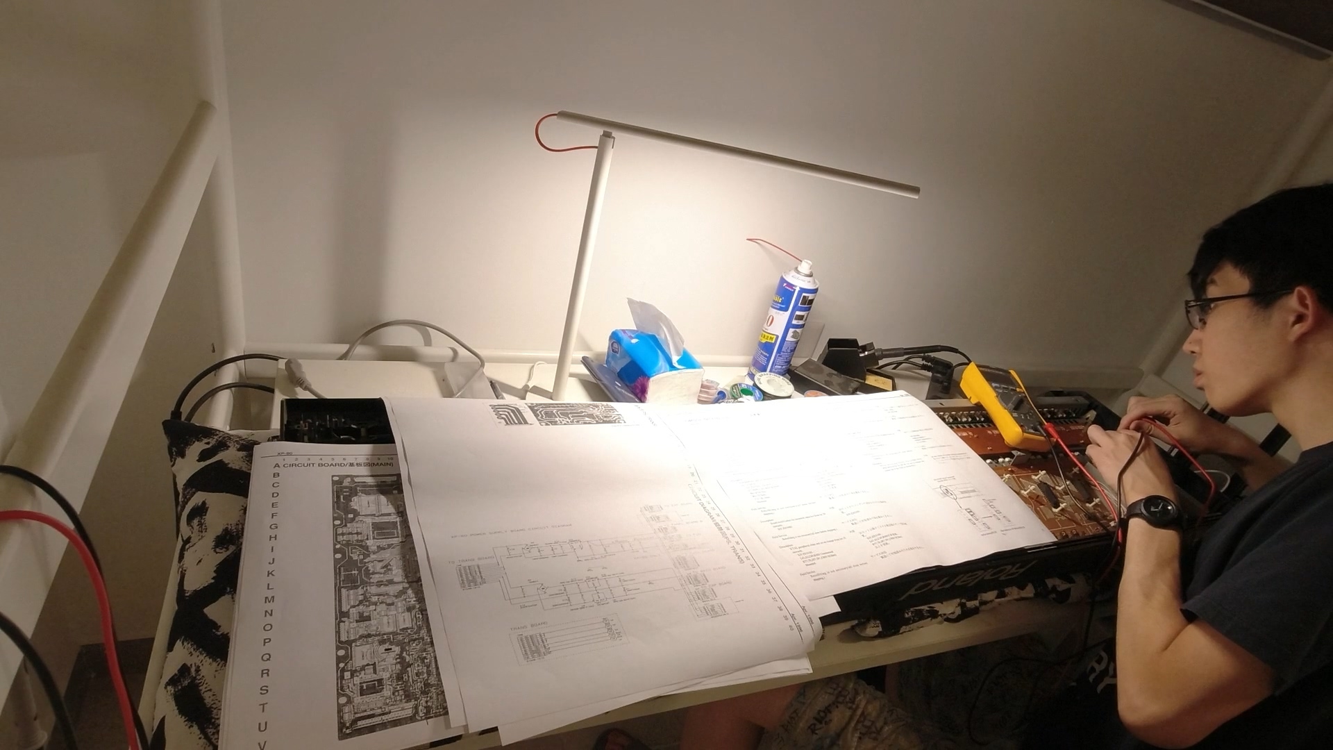
Next I soldered wires onto the PSU board, to use external power supply to test the machine. The board still didn’t boot. I kept the wires though, as further testing could be powered this way instead of using mains AC.
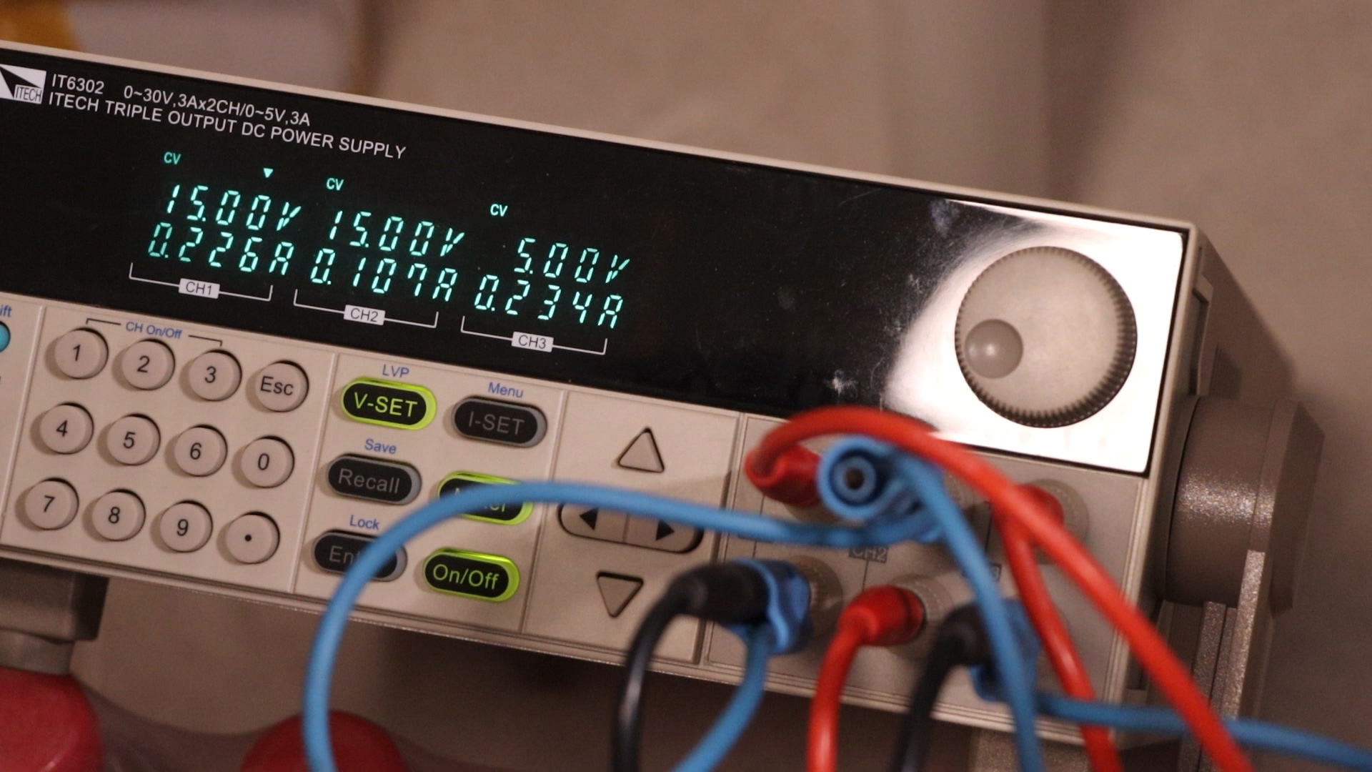
Based on the changing current at different stages during start-up, I assume the board has some action and is not totally fried.
Replacing All Electrolytic Capacitors
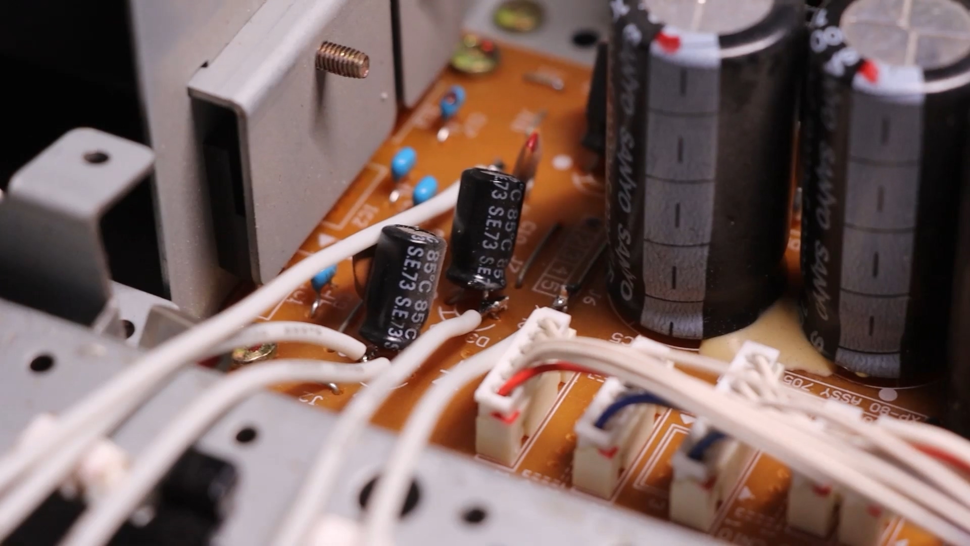
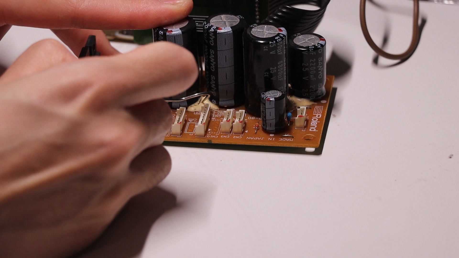
At that time I didn’t have a clear diagnosis so I went on to replace all electrolytic capacitors on all boards, which are infamous for drying out on this machine. I removed all PCBs from the synth, and measured out the diameter of some capacitors, since a certain voltage and capacitance combination may yield more than one dimension.
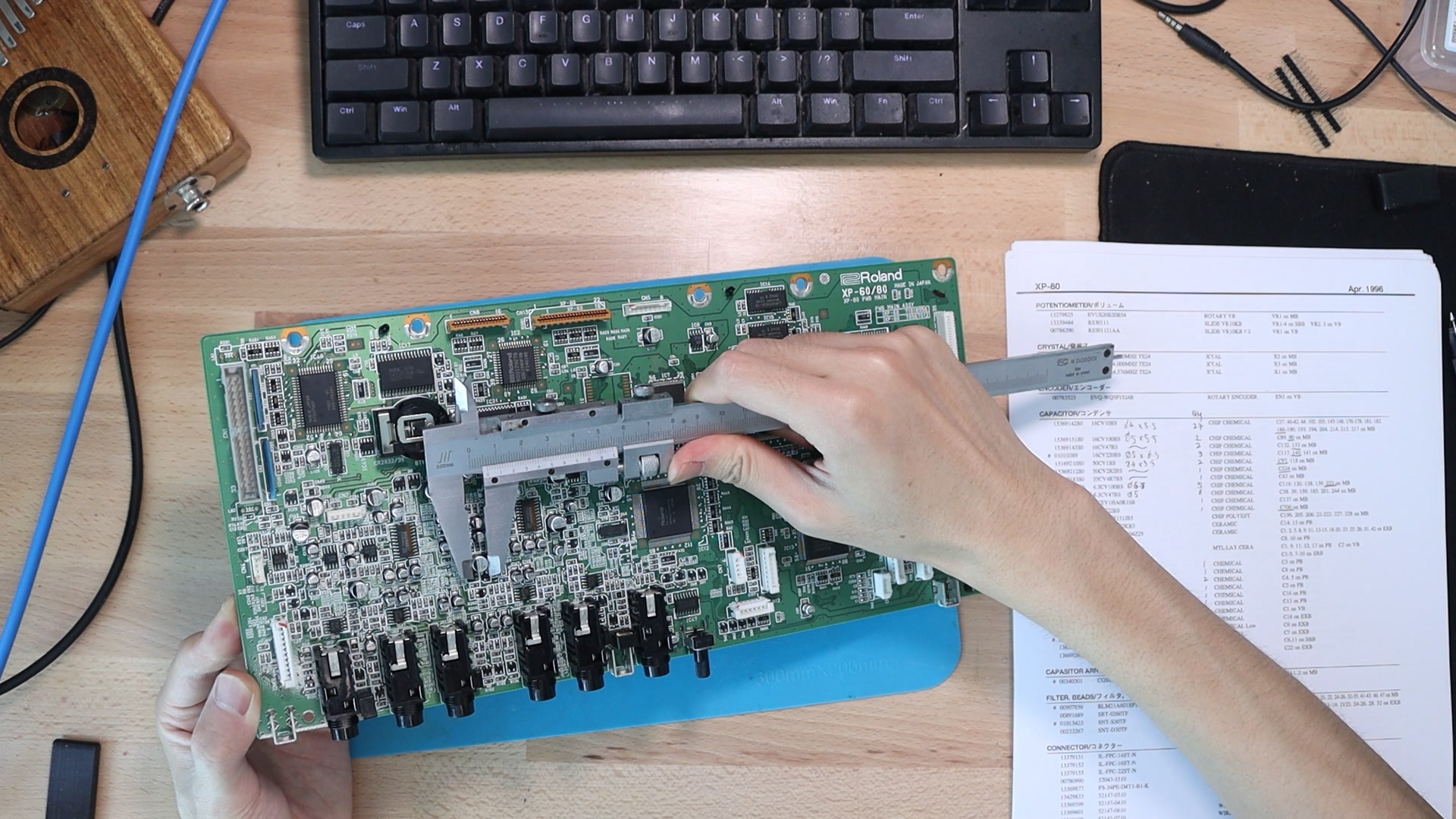
I bought replacement parts on LCSC, and replaced all electrolytic capacitors.
Of course this didn’t help the repair at that time, but in replacing all electrolytics made sure the machine will correctly function for years to come.
In the process I damaged a SMT film capacitor on the main board which is a critical part in the output filtering circuit and is very expensive. I had to buy a new one and replace it.
More diagnosing
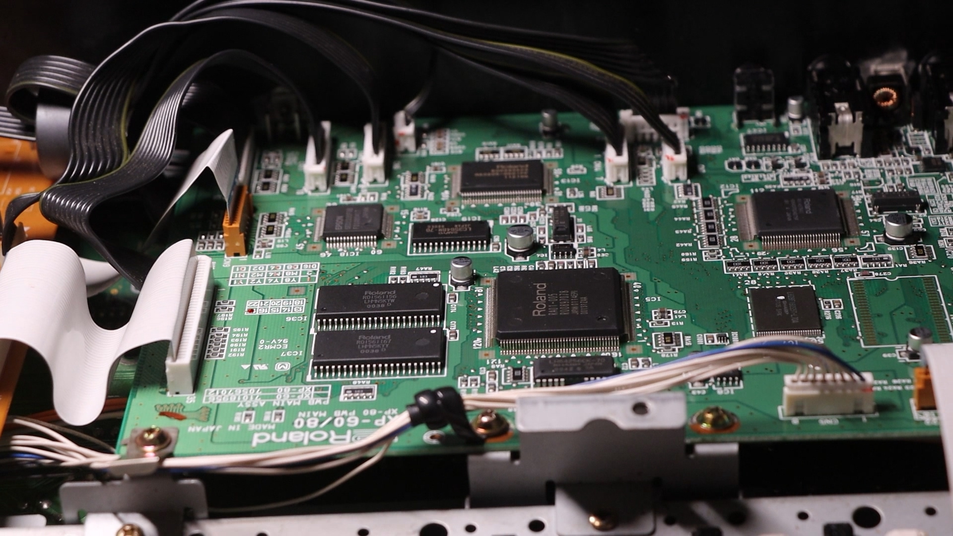
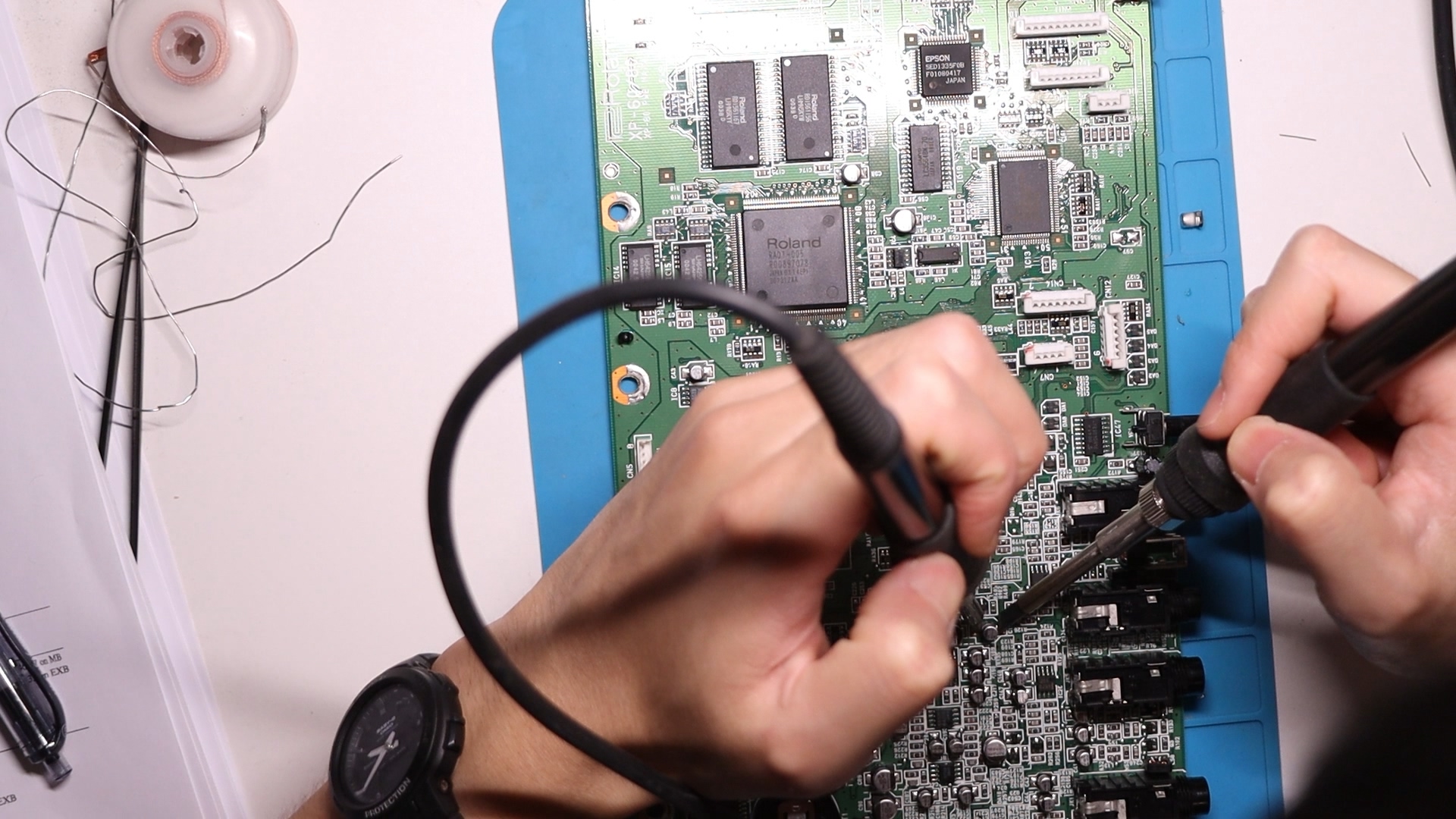
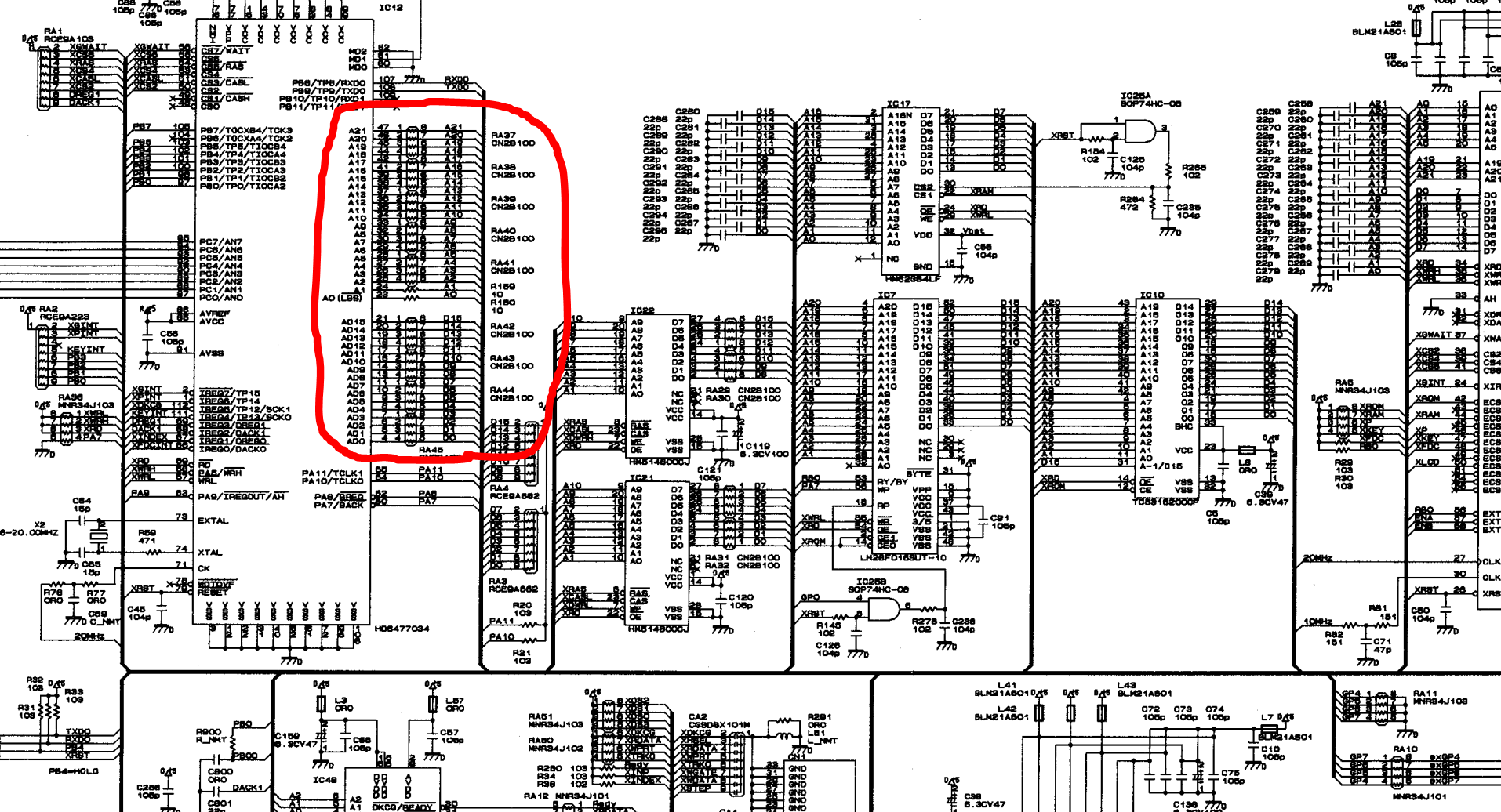
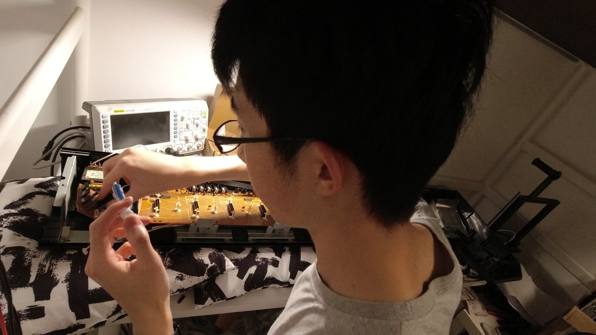
I went on to probe the data lines of the CPU, a Hitachi RISC MCU, with an oscilloscope. There were some weird waveform on some of the data lines, which I didn’t think much of it. I was assuming since the OSes were not booted, some chip may not be in a defined state so the output may be irregular.
In addition, when I tried to mount the PCB back to the chassis without the keybed installed, I couldn’t install the screws as holes were not aligning properly which I found to be very strange.
Luck Strikes
Then one day after I had a dinner together with a YouTuber who has more than 100,000 subscribers, I came back and decided to re-solder all SMT chips. After I did that, the synth just magically booted.
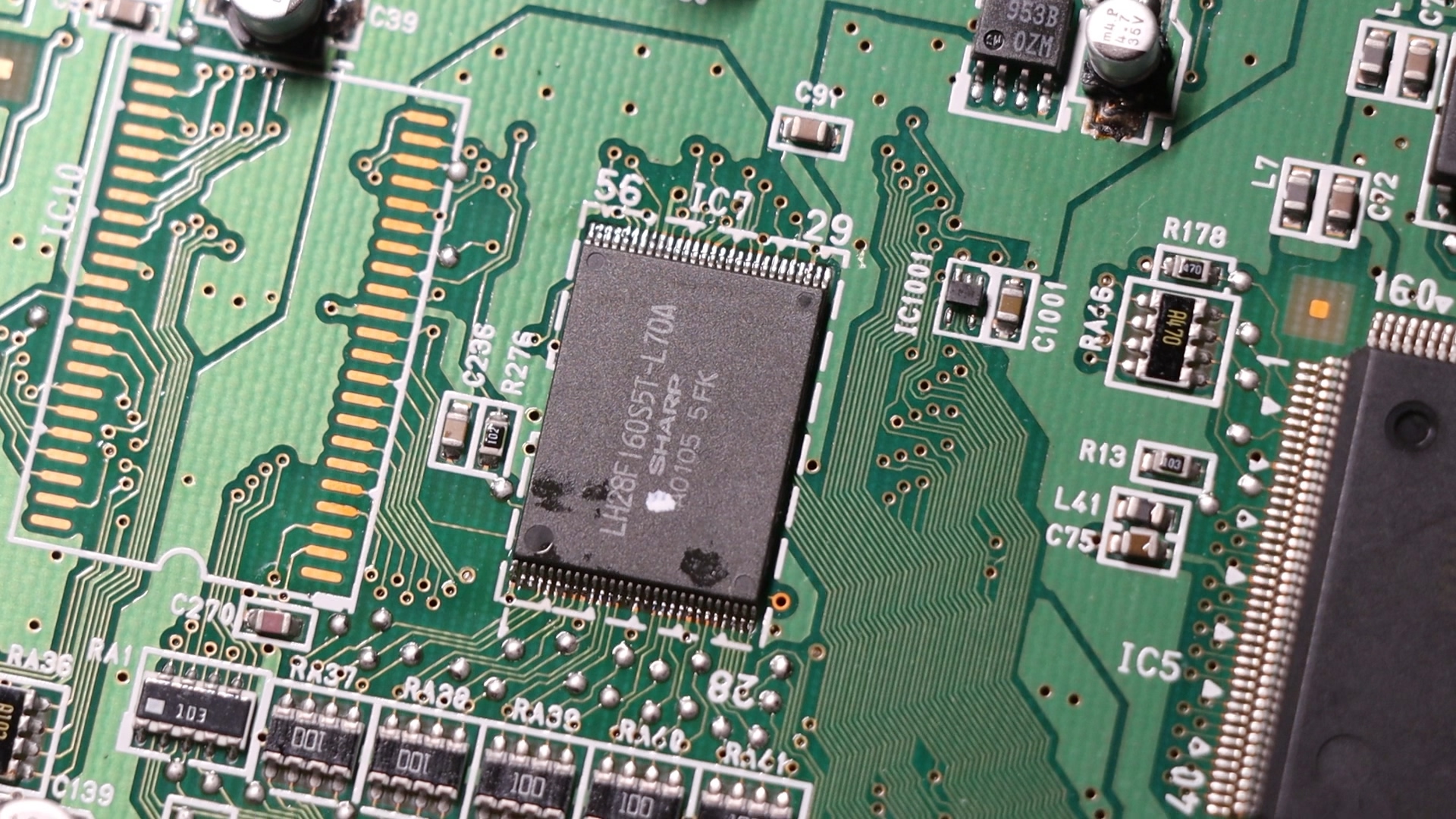
It turns out the strange waveform on the data lines are probably due to a bad SMT solder joint in either the CPU or more likely, the NAND flash. The waveform sort of looked like a RC waveform which also makes sense.
The bad contacts were likely caused by mechanical stress, induced when previous owner or repair personnel (I’ll explain this later) removed the keybed and leaving the PCB on the chassis. The keybed shares some mounting point with the PCB. Without the keybed mounted, some mounting plates are in a tensioned state and put all the stress on the PCB, causing it to warp. This explained why the PCB couldn’t be installed when the keybed was removed.
I couldn’t remember where I saw it, but there was a forum post where the OP said his XP-80 would work when the back cover is removed, and won’t boot when back cover is installed. He suspects EMI issues. Now we know it’s probably caused by mechanical stress.
More Problem
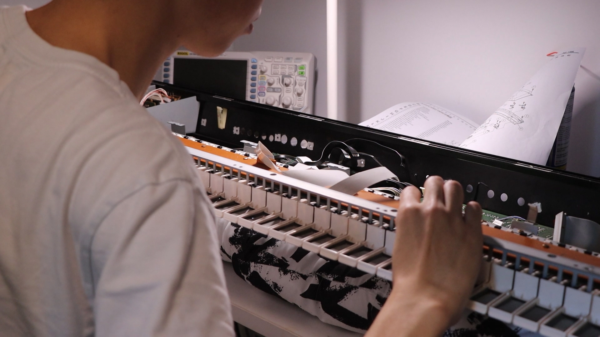
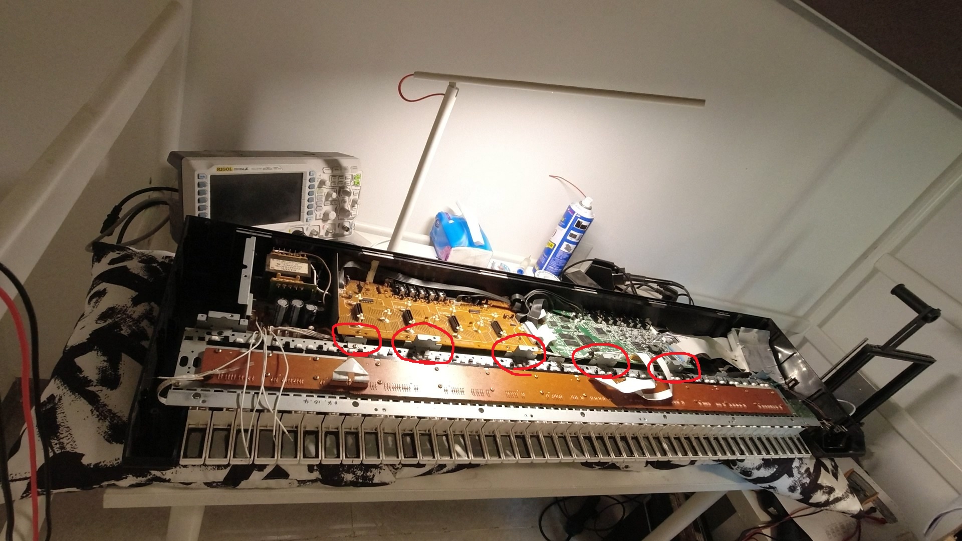
As the machine now boots fine, I tried to play something on it. Turns out some keys weren’t working, and were marked on the keyboard.
Further testing with a DMM revealed that some connection is broken between the keybed PCB and the main board. As keys are arranged in a scan array, keys are broken at set interval.
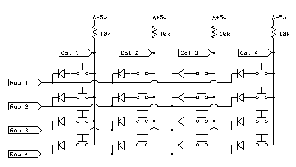
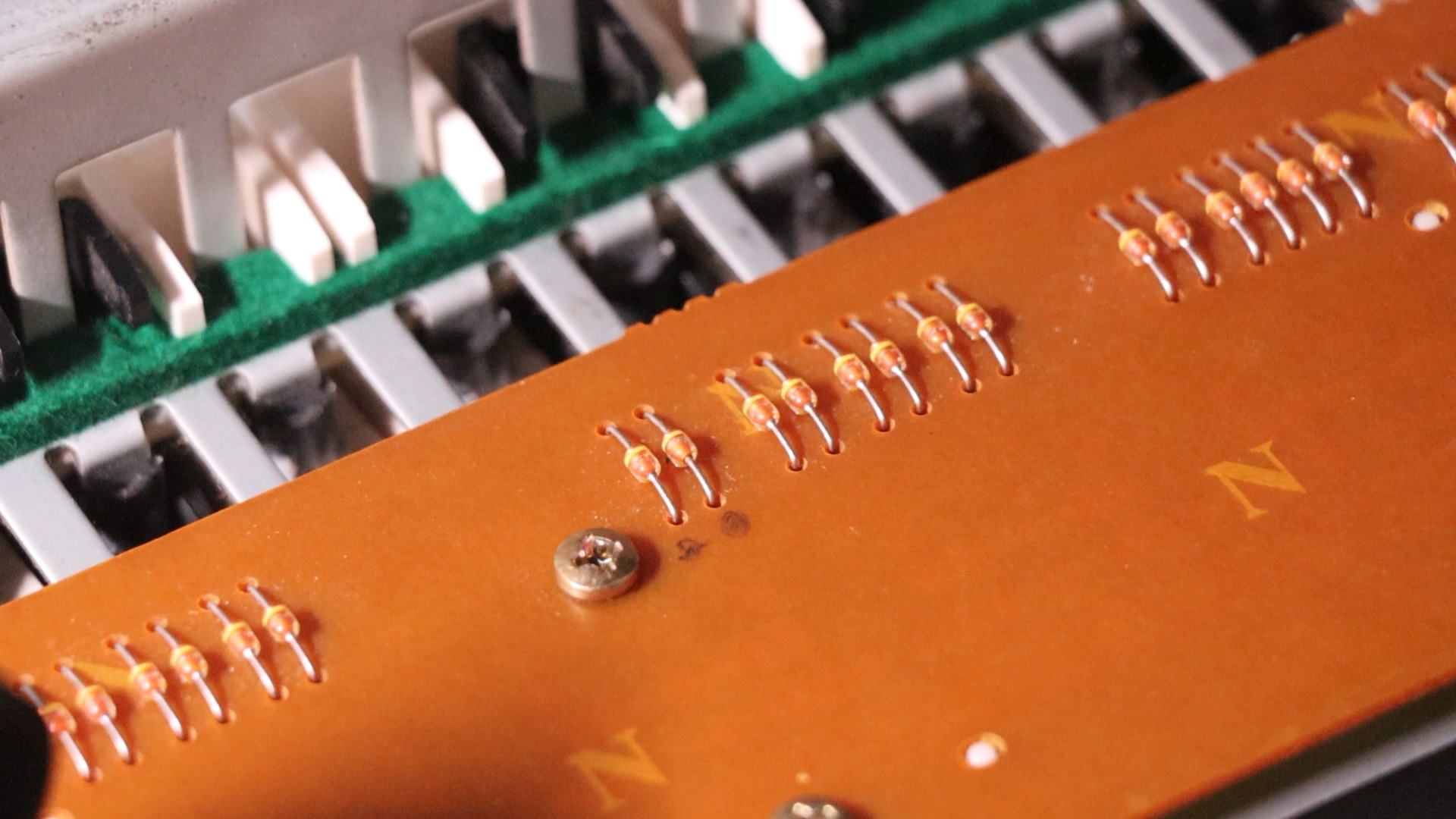
The previous repair attempt successfully detected the broken contact, since they marked all diodes that does not connect to the main board.
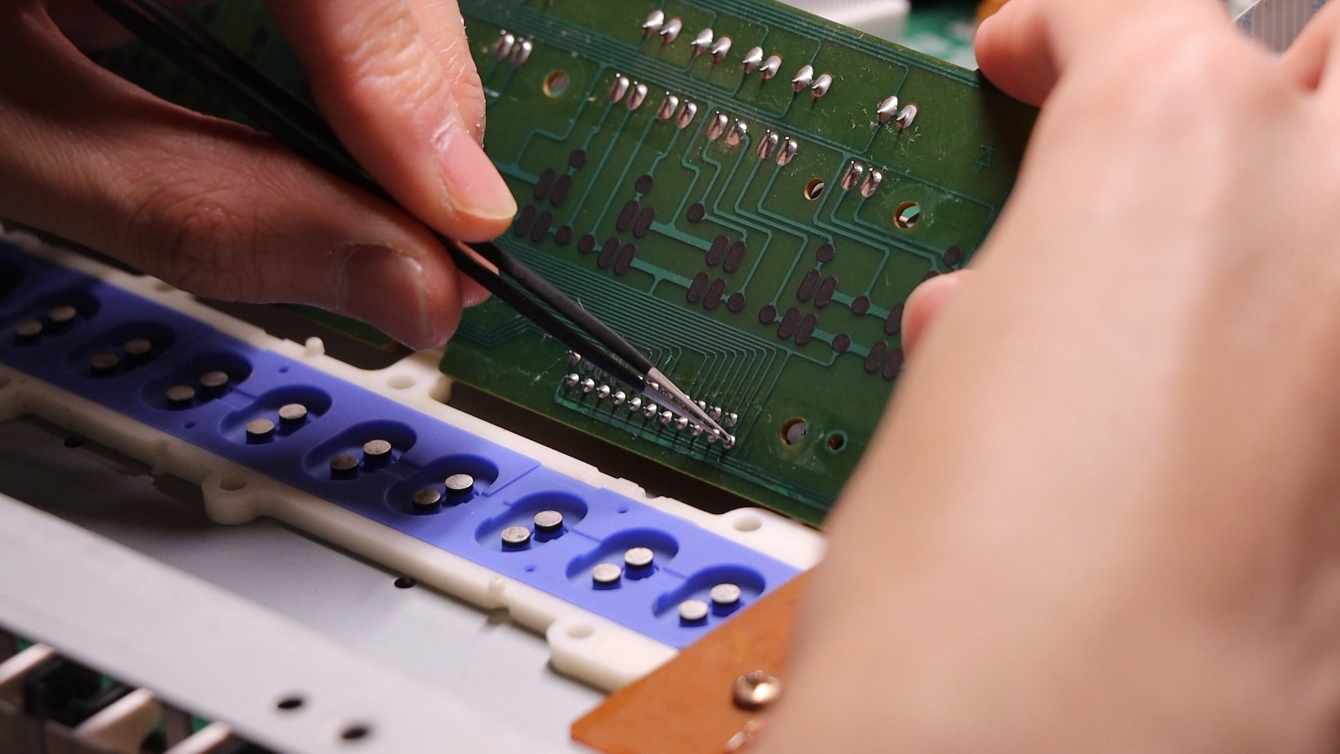
But they never found where it is, and in the process put too much stress on the main PCB. The problem was a cracked solder joint on the FPC connector on the keybed board.
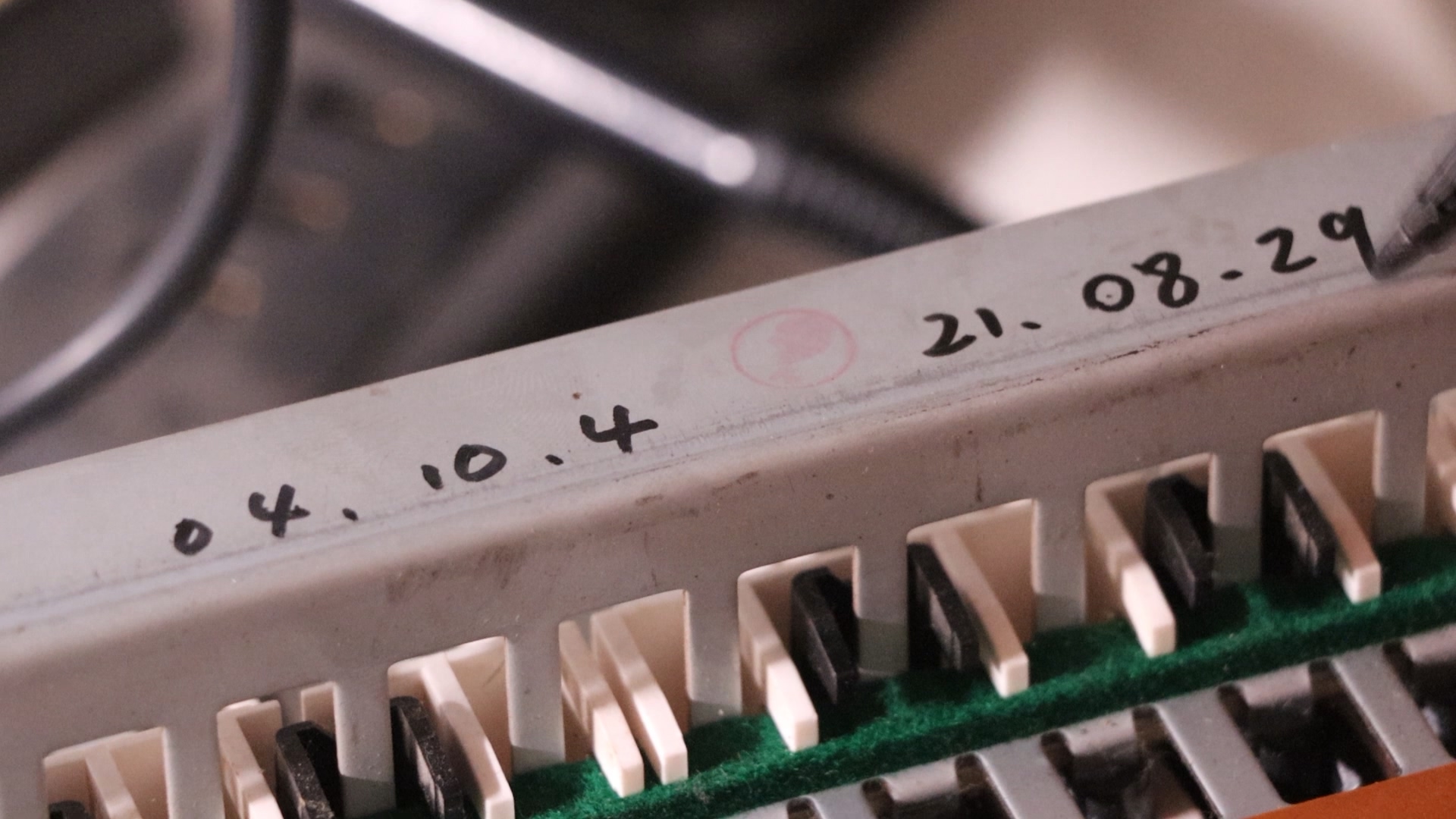
After re-soldering the joint, all keys went back to working order. I wrote my repair date next to the previous repair marking, which was 17 years ago.
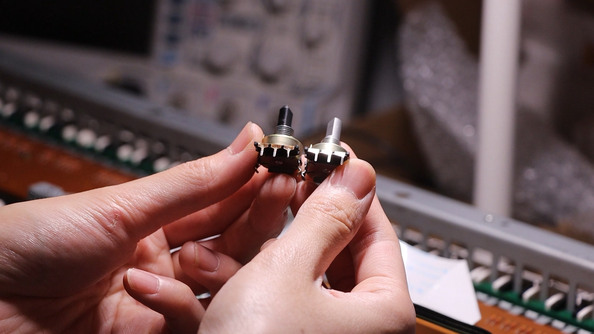
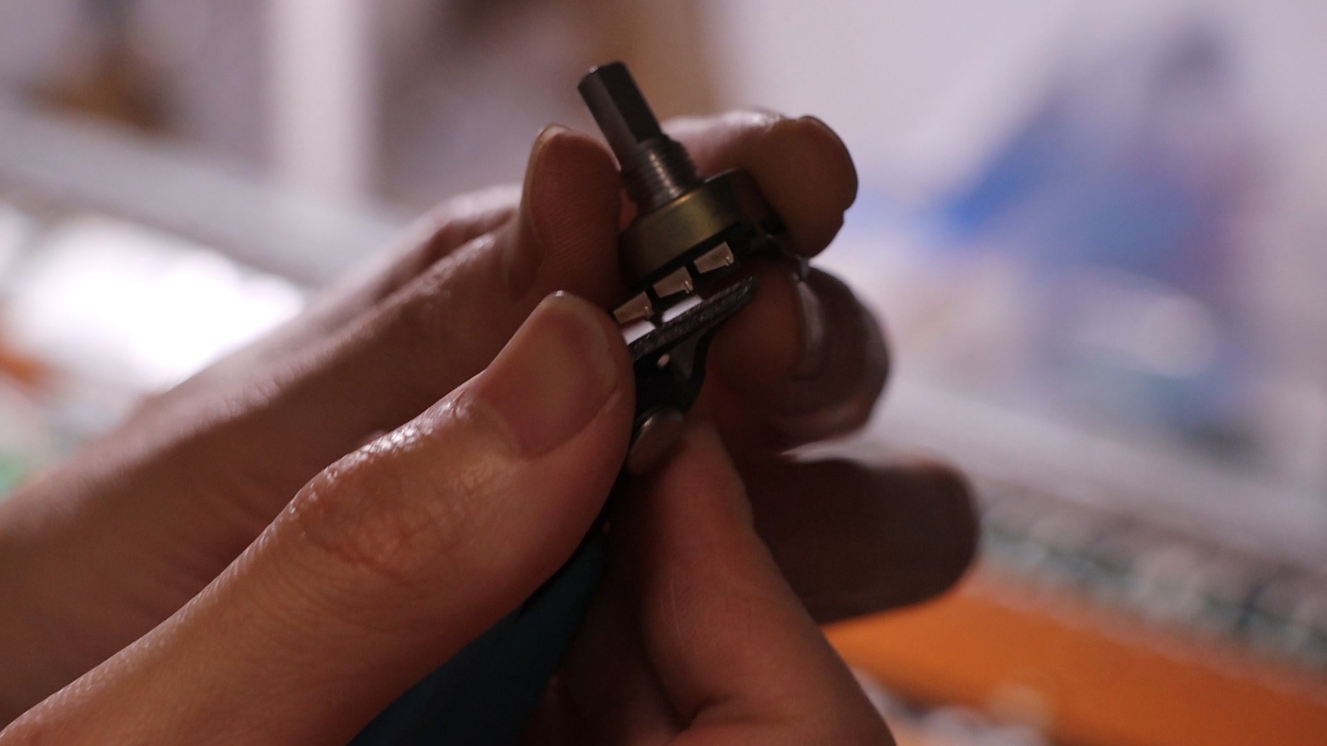
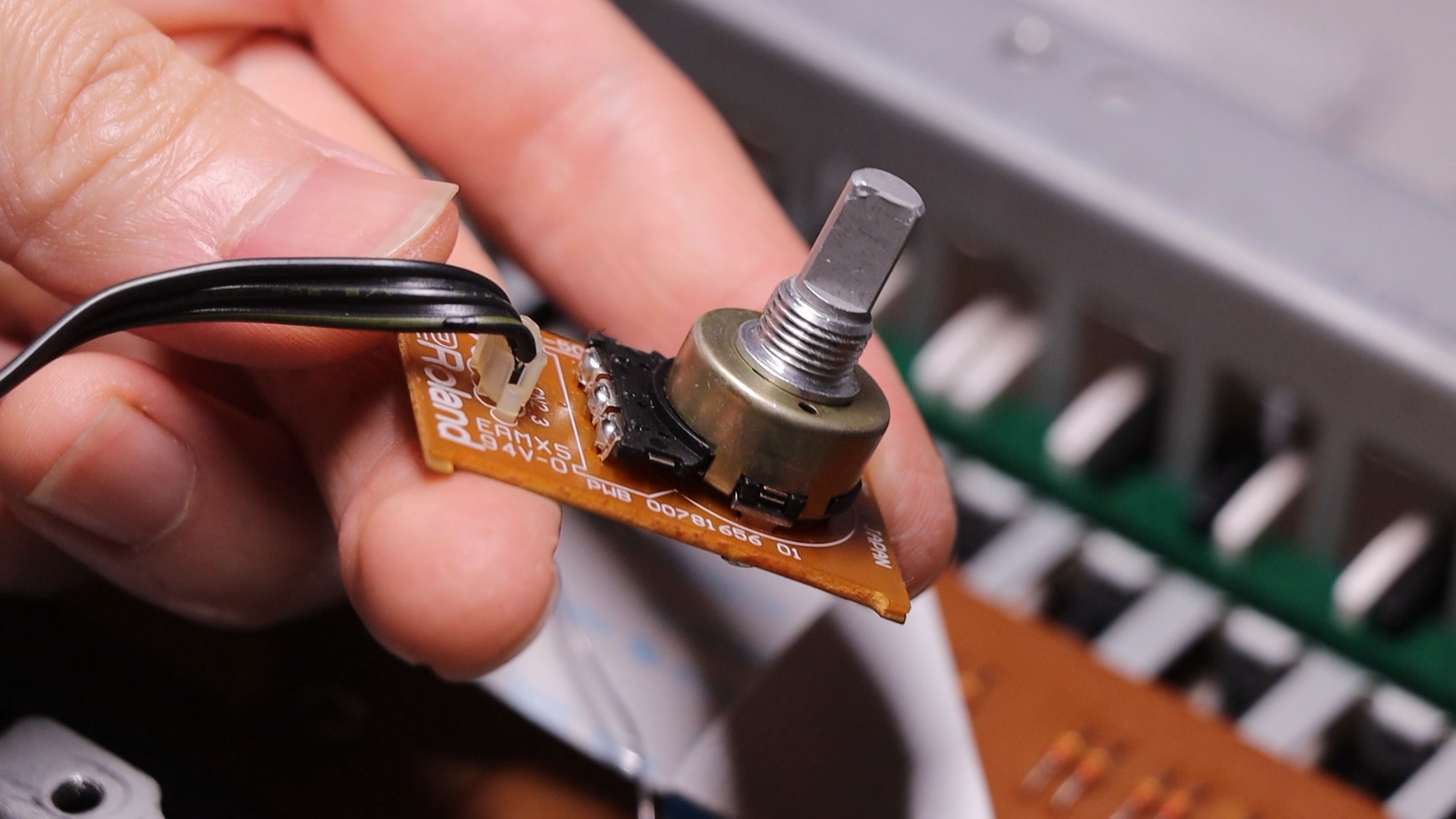
Another problem was that the rotary encoder was acting up. It was a Panasonic EC16 with plastic shaft. I bought a similar looking one with metal shaft but turns out to have different pin shape. I had to modify it by cutting its pins and connect it to the PCB pads with pins extracted from pin headers.
Improve with a USB Floppy Emulator
If you have some interaction with retro-computing community, the name GOTEK must ring a bell. This is a commonly used floppy drive emulator with USB connection for use with USB thumb drives.
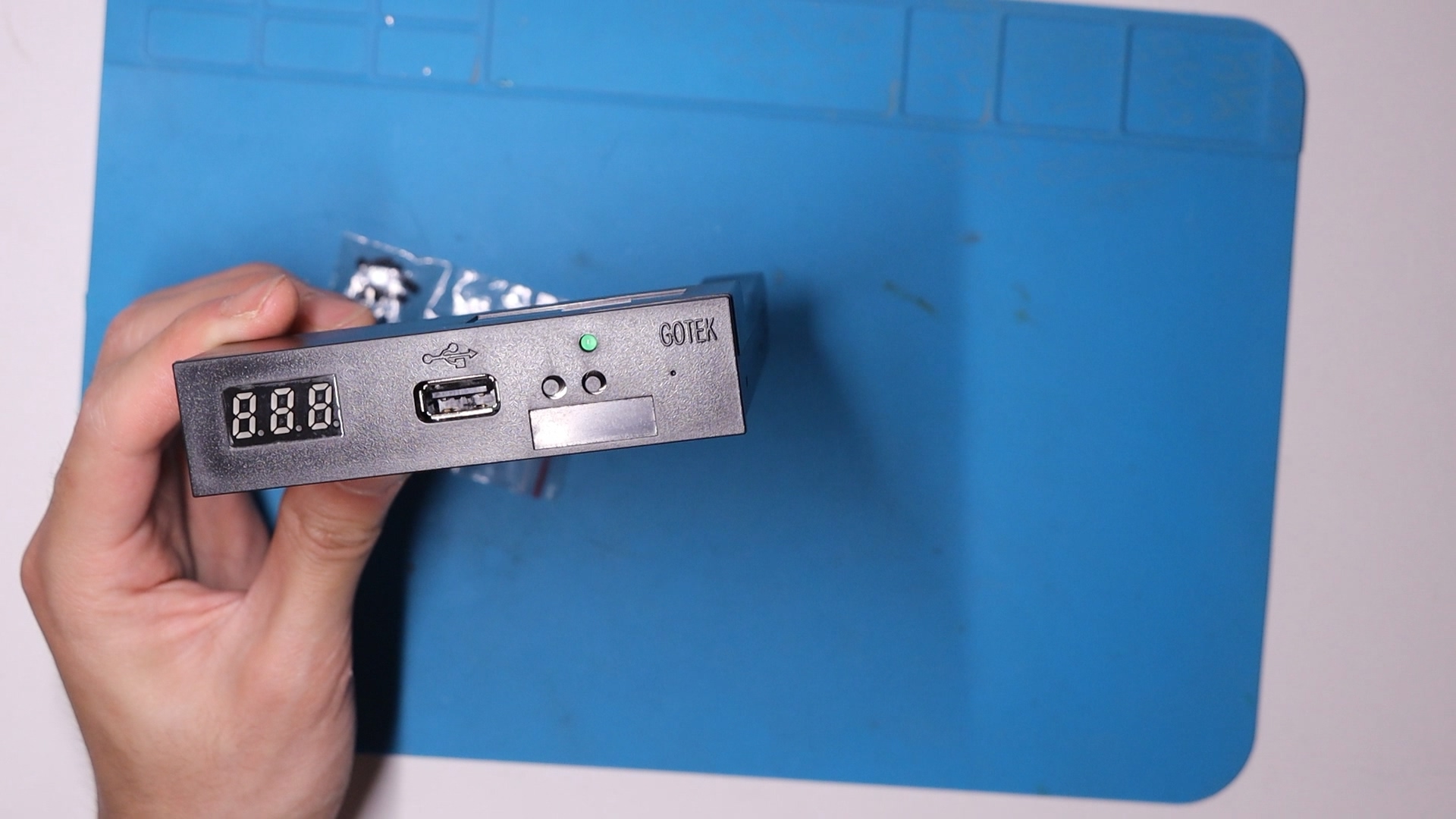
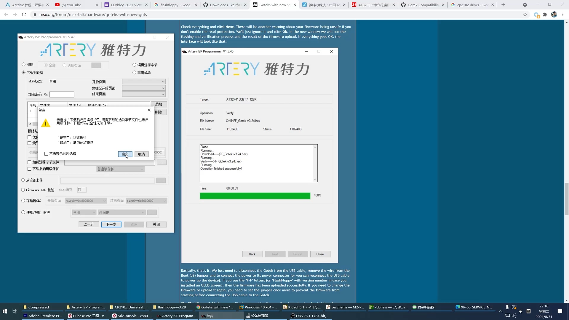
I got one with the model number of SFR1M44-U100K, but it was the newer version which has ARTERY MCU in it instead of STM32 due to chip shortage. I was going to use FlashFloppy firmware. At that time their guide suggest the usage of USB bootloading, but I didn’t have a USB A-to-A cable. So I went on to try the serial method.
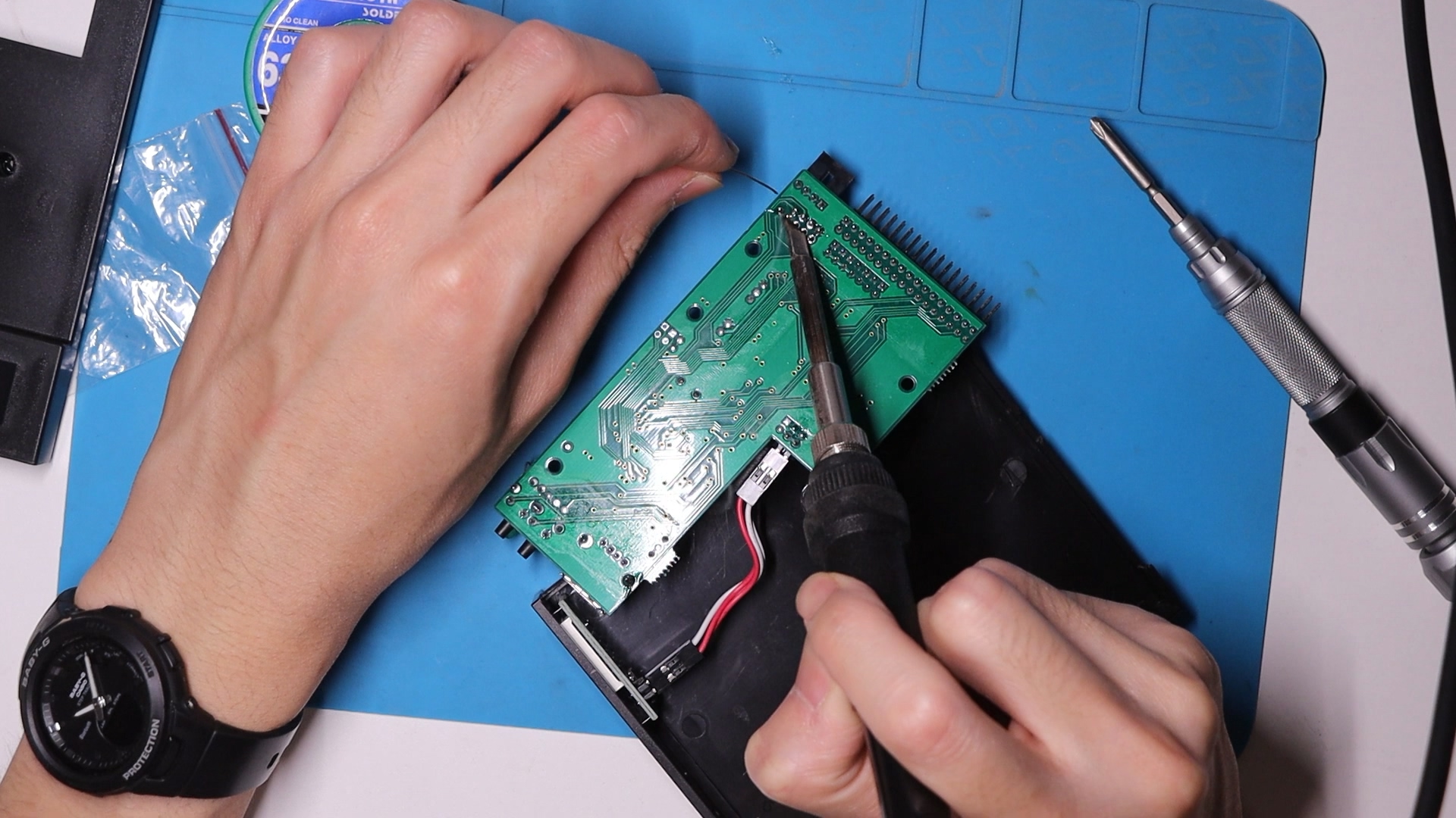
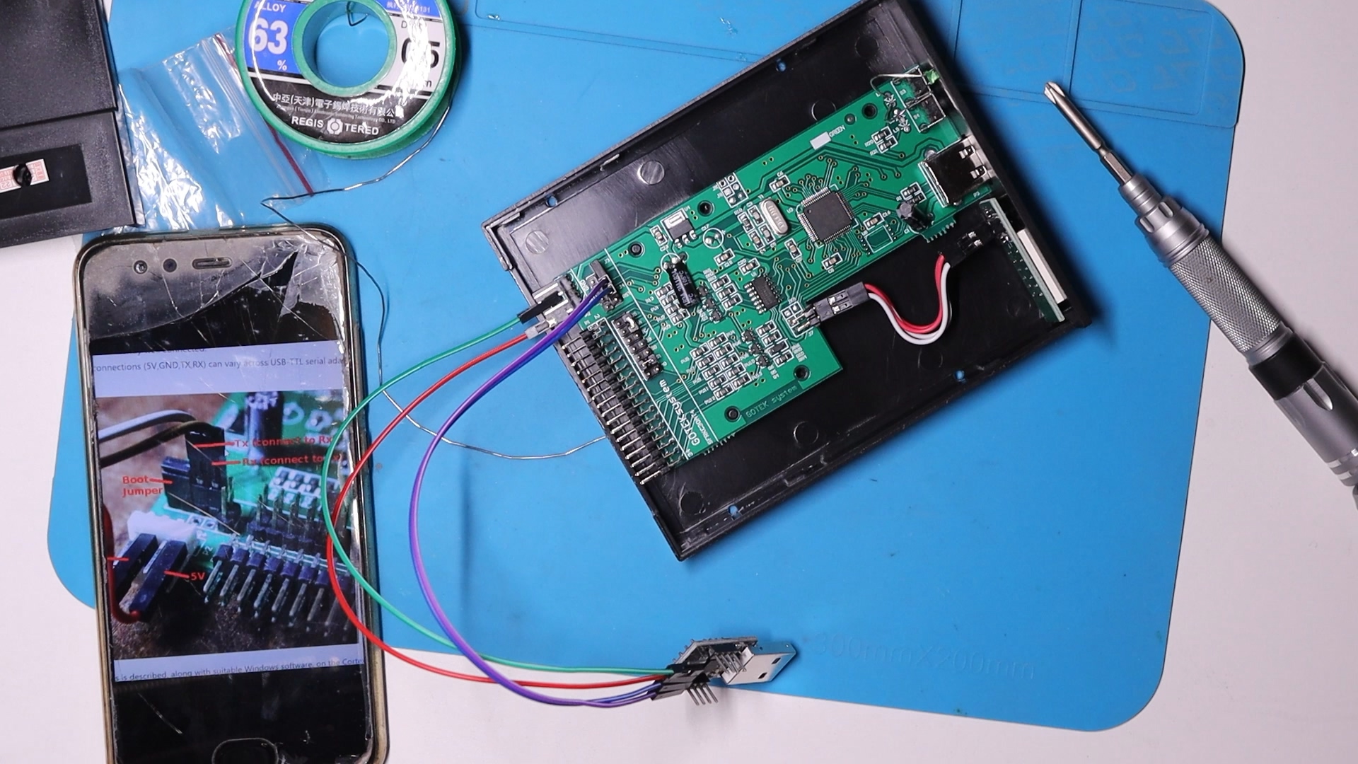
And it worked out fine. I successfully flashed FlashFloppy firmware.
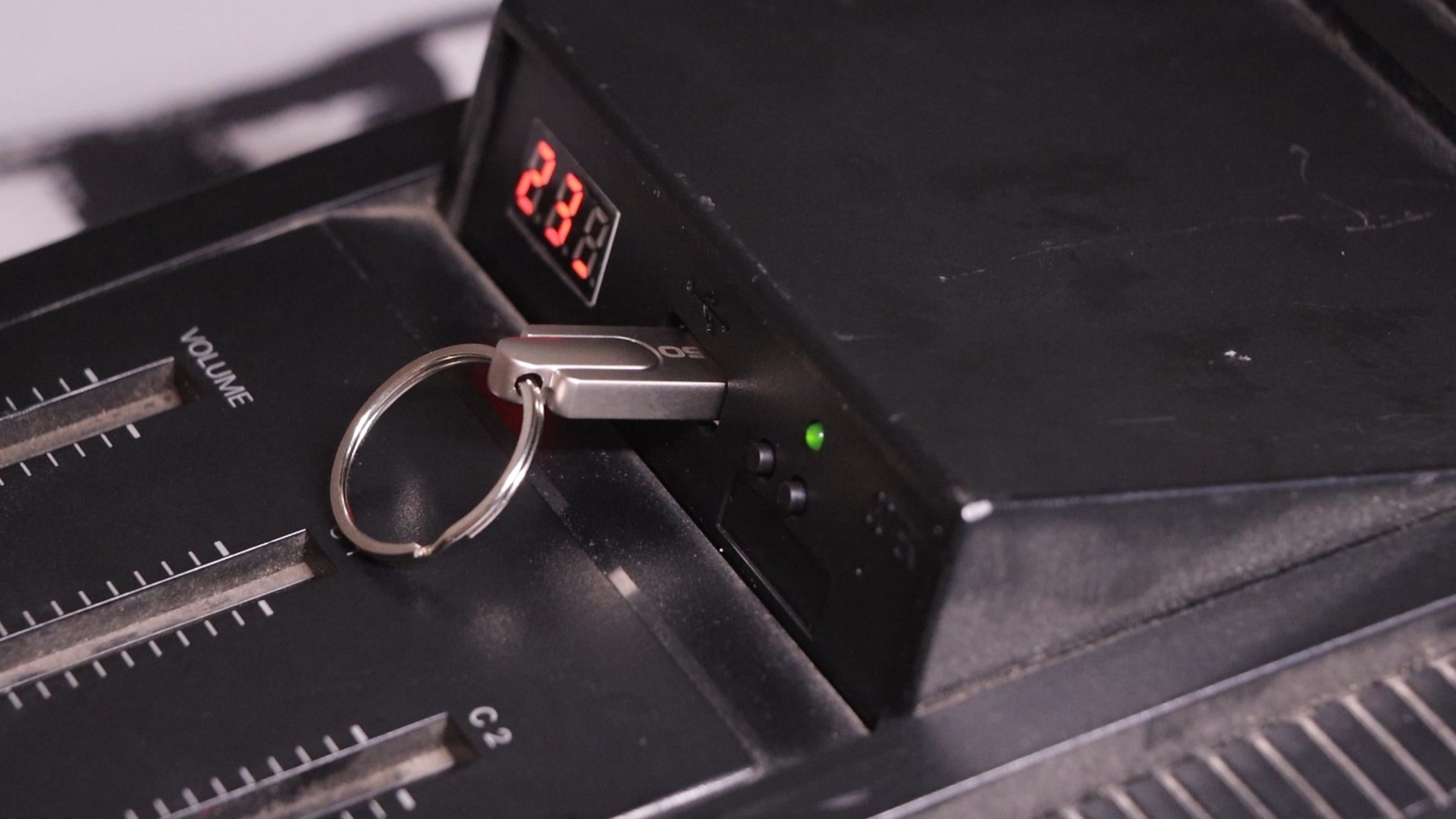
Then I installed the emulator into the XP-80, removing the old floppy drive.
On the way to reassemble the synth I put some thermal paste between the power supply LDOs and the heatsink. I used Arctic MX-4 which was way overkill.
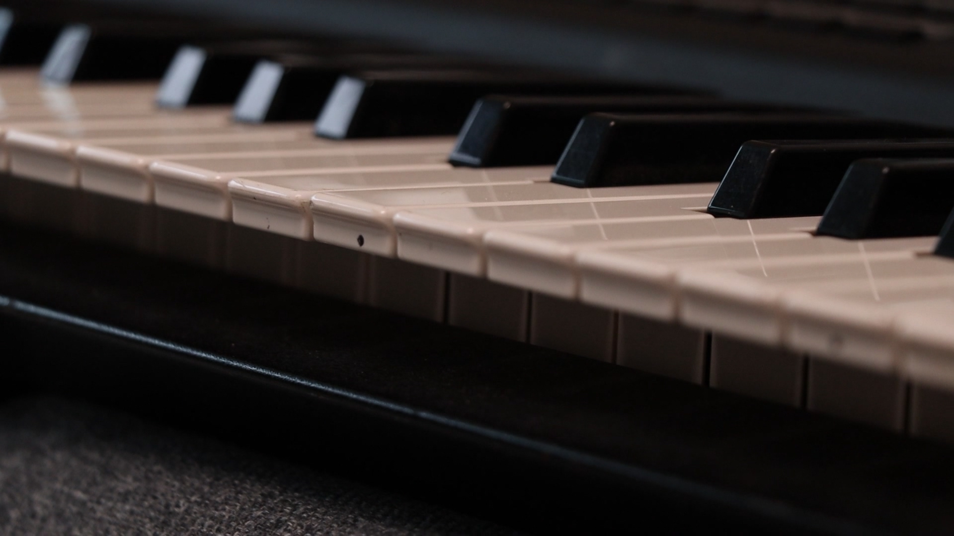
After reassembling everything, the repair is finished. Although my unit doesn’t have any expansion card, it still sounds very nice. The menus and UI are well thought out, very intuitive and easy to use. Albeit being 20+ years old, this synth still rocks.
Thoughts and Notes
- Start with the obvious
- If the service manual tell you to remove something first, it may be doing so for a reason
- For the XP-80 and other Roland synths from that era using a similar mechanical structure, DON’T REMOVE KEYBED BEFORE REMOVING PCB
Hi
My XP80 boots up, but there is absolutely no sound coming out of any of the outputs, including the headphone outlets nada.
I bought the keyboard to a local Electronics guy and he’s changed a bunch of capacitors but still hasn’t been getting any sound to come out. Any thoughts on what he might be able to do?
Thanks
Russ
Hi:
If power supply has been checked, use oscilloscope to see if there’s any activity on the DAC input and output.
Also have you used the test mode to see if there’s any sound at all during audio test and keyboard test?
Hi, I’m the one who bought one of the SR-JV Wi-Fi cards from you, and I was curious about the repair of this XP 80, because I’m currently working on its little brother, the XP 50. So, my question is: why did you have to flash the Gotek emulator? Do I have to do that if I want to install one on my keyboard, or was it a specific problem with that unit?
Greetings from Venezuela.
Hi:
Not necessarily, you can use the factory shipped firmware. The original GOTEK firmware is difficult to deal with in terms of using floppy images or managing files. I’d recommend you flash your GOTEK with the free version of HxC, or FlashFloppy, in order to make the best use of your GOTEK hardware.
I understand. Thanks.
Hi – David here from the UK.
Thank you for some very useful information. I found a couple of capacitors were loose on the main PCB. It’s a bit confusing because although they have the same markings on the top of the case, they are showing different values in the circuit diagram? Specifically, C38 and C159.
C38 is shown as .015uF 50v and C159 is 10uF 16V. I cannot find direct equivalents here in the UK, so I’m not sure what I should replace them with. Any ideas please?
Regards, David.
Hi:
Those are power filtering capacitors, and you’ll be fine with other alternative capacitors as long as they have a voltage rating of at least 6.3V. Regarding the schematic, those are both labelled 6.3V 47uf in the service notes that I have.
Nice to read that there are still people who are trying to give the Xp80 a new life. I came to your site because I am also working on an Xp80. The capacitors have all been replaced. What I now notice is that the XP sometimes shuts down and shows a blank screen. What I suspect is that one of the legs of an IC is hanging loose somewhere against the PCB and is starting to expand due to the heat and lose contact. Today I am going to look at all the SMT processor ICs with flux and a little tin and hope that this will solve the matter. Apparently this is a common problem with Roland devices from those years. The Jx305 also has these problems that the SMT parts dare to come loose. greetings from Holland.Pi
Hi Pieter, thank you for your comment. The most detrimental problem I later found out was mechanical stress induced by the chassis. Eventually I had to open up the synth again to re-solder the flash IC once more, which I did together with the screen change. I did some “bodywork” to correct the tension and hopefully I will not have to do this again.
Greetings from China
SALUDOS DONDE COMPRO LOS CHIP DEL XP 80
saludos, donde puedo comprar la placa madre del XP 80 ROLAND
Hallo,
thank you for this good blog.
What Flashfloppy settings did you need to make on the floppy emulator to make it work? [Jumper and FF.CFG wise?]
Hi Andreas:
Default jumpers would work. For flashing using serial method I followed guides for STM32 units, use the Artery bootloading program instead of STM one. I did not recall making modifications to the FFCFG. Unlike W-30 the XP series is compatible with a wide range of drives.
As can be seen in the photo, mine has a jumper on S1. Works fine. The other one is a spare.
mi teclado tiene ruidos como y da unos cuetasos. ya cambie los condensadores de la fuente de poder , cambie los jac , el problema es en la tarjeta madre. que capacitadores tengo que cambiar o otra cosa más. por eso necesito el plano de xp80 roland….gracias
Hola! No hablo Español lo siento.
You can download service manual here
http://www.synfo.nl/servicemanuals/Roland/XP-80_SERVICE_NOTES.pdf
You should try to replace the audio AC coupling capacitors first.
saludos, porfa necesito el plano del sistema eléctrico del teclado xp80