Table of Contents
What is this
Github Repo: https://github.com/ryanzheng97/phantom-power
(Will make public once patent has been dealt with)
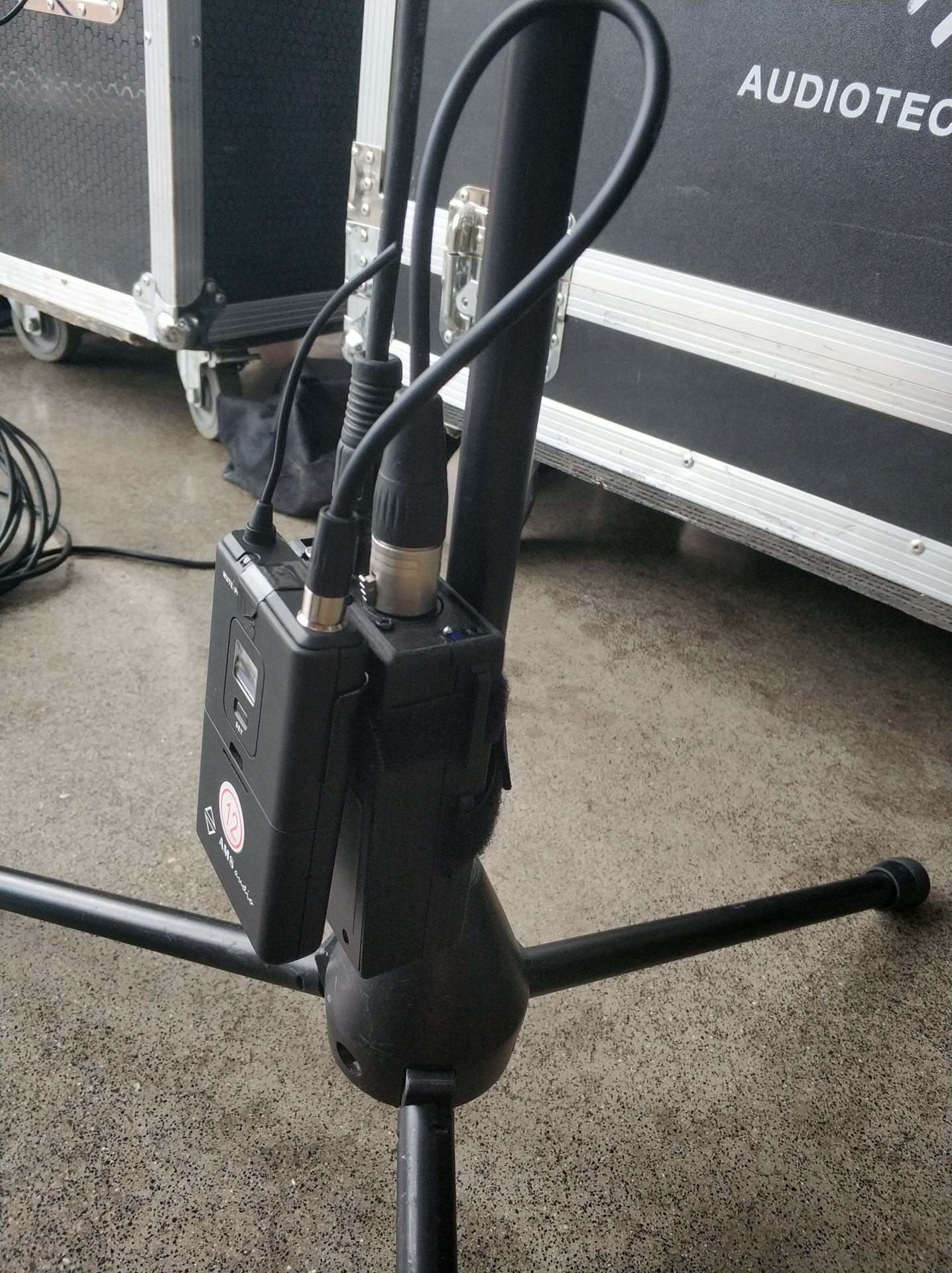
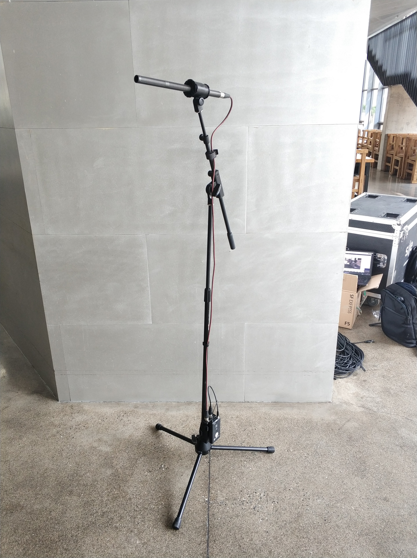
This is a 3-AA-battery powered phantom power supply. It was intended for use with wireless microphone beltpacks to provide high quality 48V phantom power to large condenser microphones and enable them to be used wirelessly, or as a standalone unit. It’s also suitable for DI boxes, small condenser microphones and anything requiring phantom power.
This is a complete design with schematic, PCB and enclosure. Files are production-ready, with BOM. Design of this project begun in 2019 and final test was done on December of 2021. Batch production was planned but hasn’t been carried out, as newer wireless microphone beltpacks has begun to incorporate built-in phantom power circuits (although usually not at full 48V), and COVID has had a major impact on touring industry.
The Specs
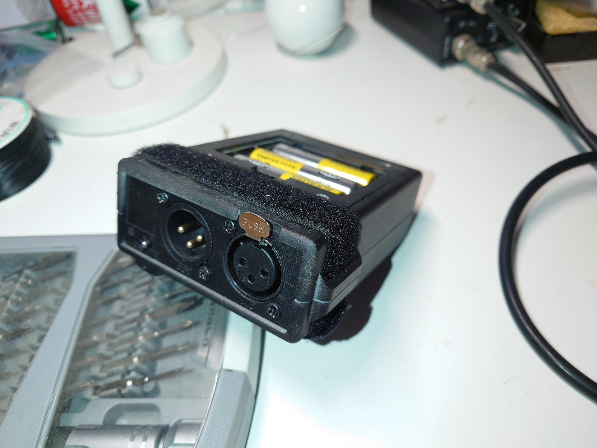
- Power Source: 3x AA Batteries, alkaline is recommended. Ni-Mh rechargeable can also be used.
- Battery Run Time: depends on load and actual battery capacity, 5 to 72 hours typically
- Battery Indicator: yes, two LEDs for normal and low battery
- Power Output: IEC 61938, 48VDC ±2V
- Phantom Resistor: 6.81K
- Current: up to about 14mA at short-circuit
- Noise: < 100uVpp
- EMI: not tested
The Design
Overall Design
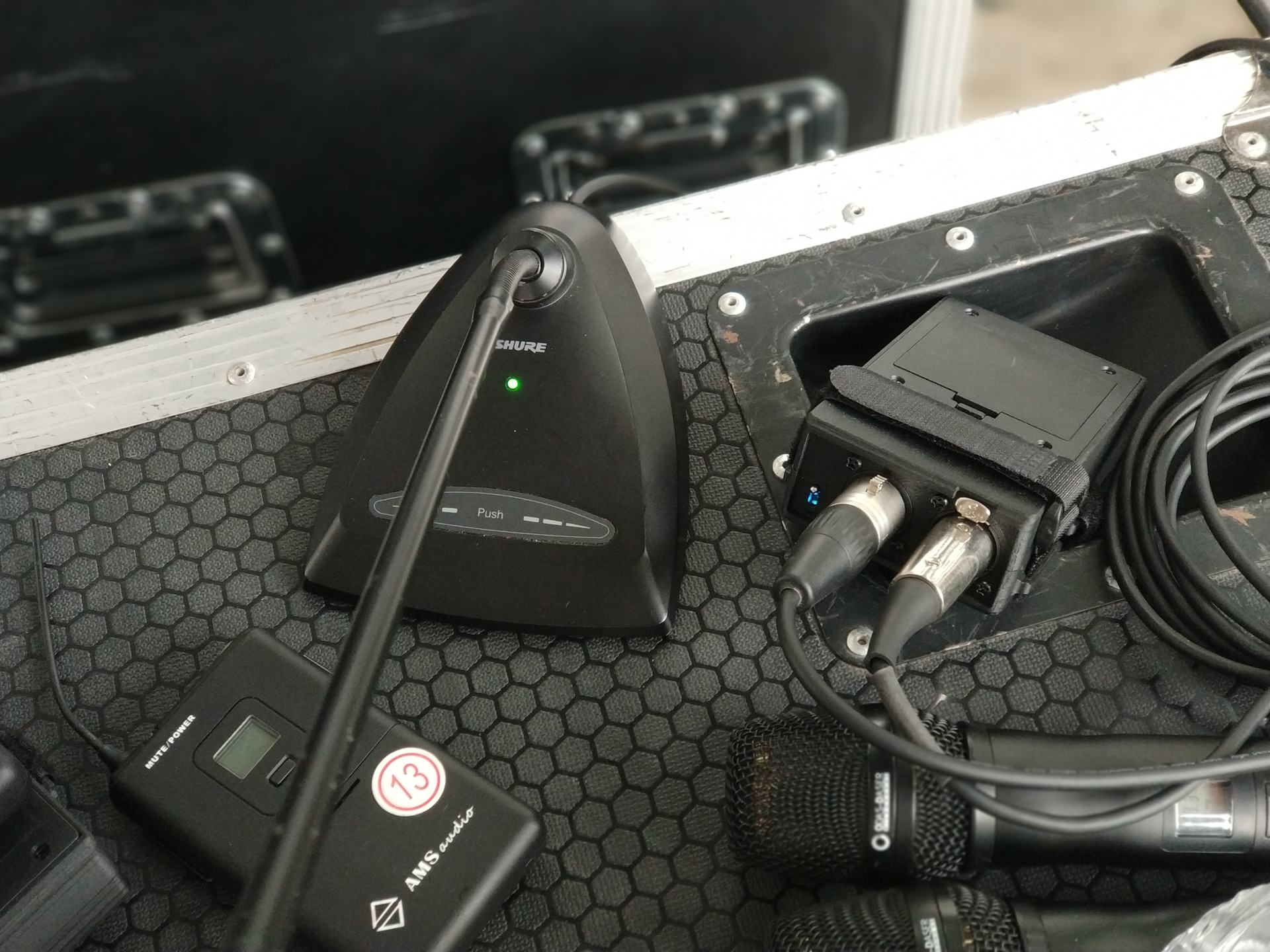
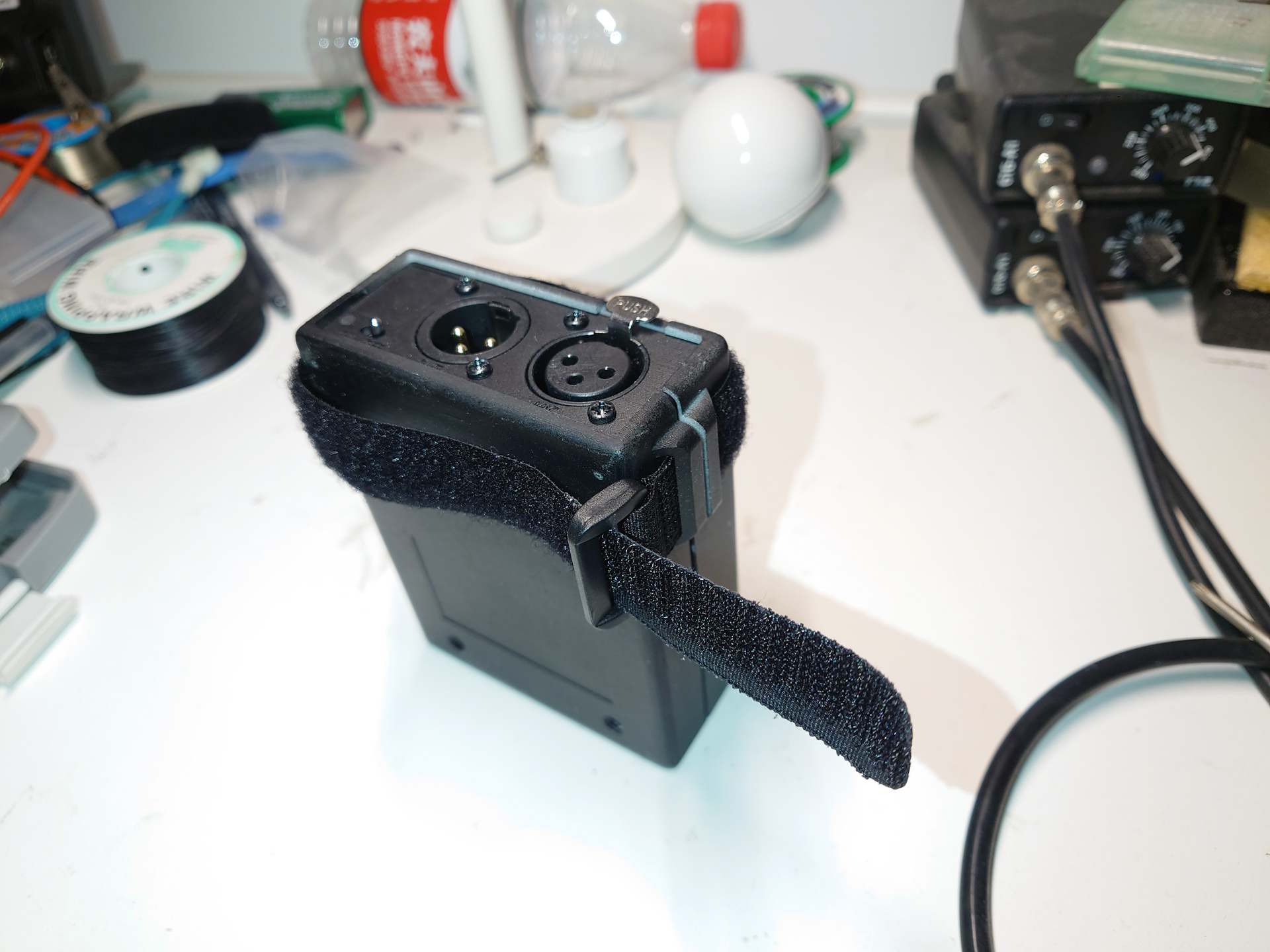
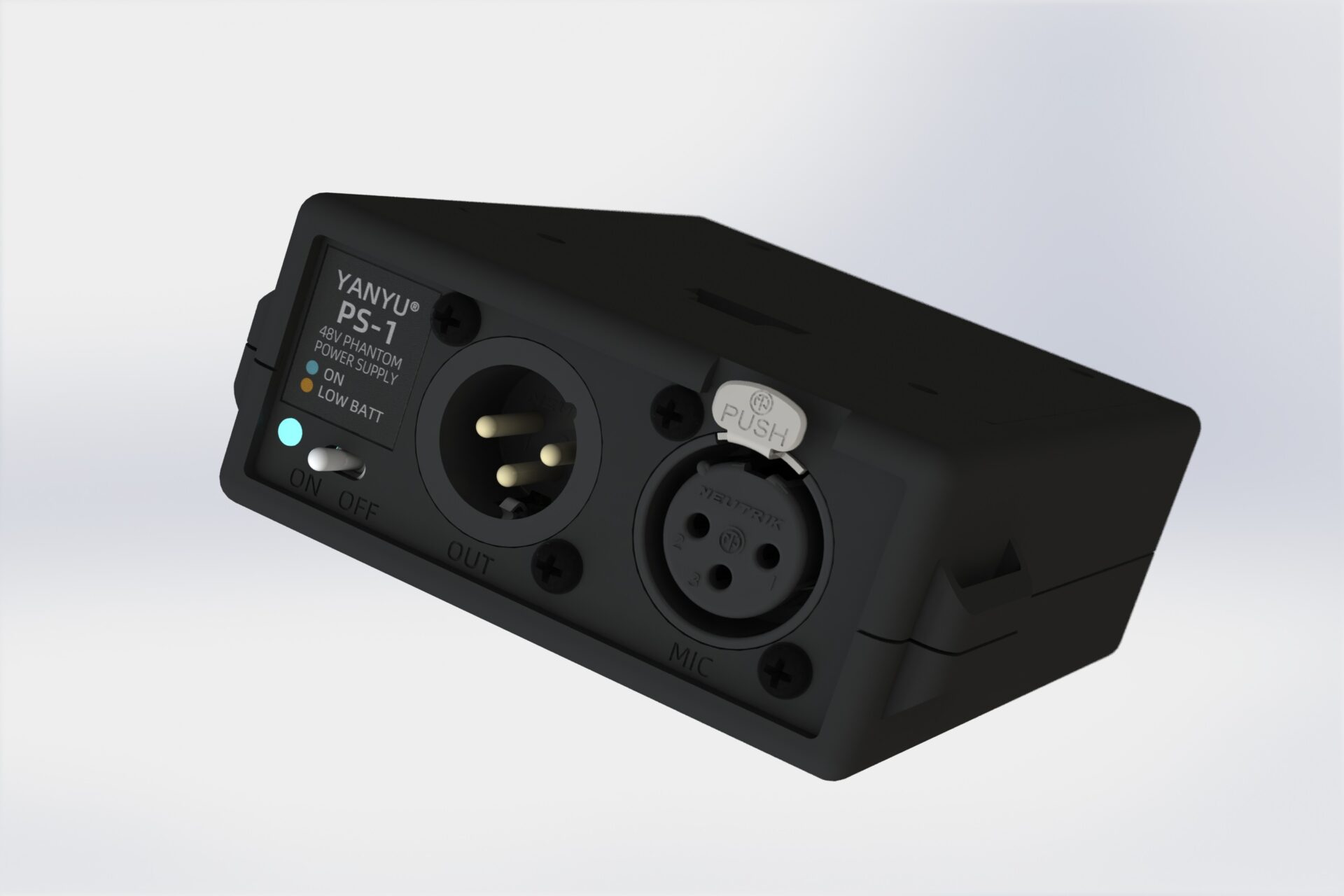
A simple power supply box with XLR-in (connects to device requiring phantom power), XLR-out (no DC bias, connect to audio input of next stage), a power switch and a battery voltage indicator. The switch is partly recessed to avoid accidental operation. The colors of the battery indicator are ice-blue and orange, which are color-blind friendly. On the side of the box are 2 ears where you can thread in a hook-and-loop nylon cable tie to form a loop and strap the box to wireless beltpack and microphone stand or other fixation points.
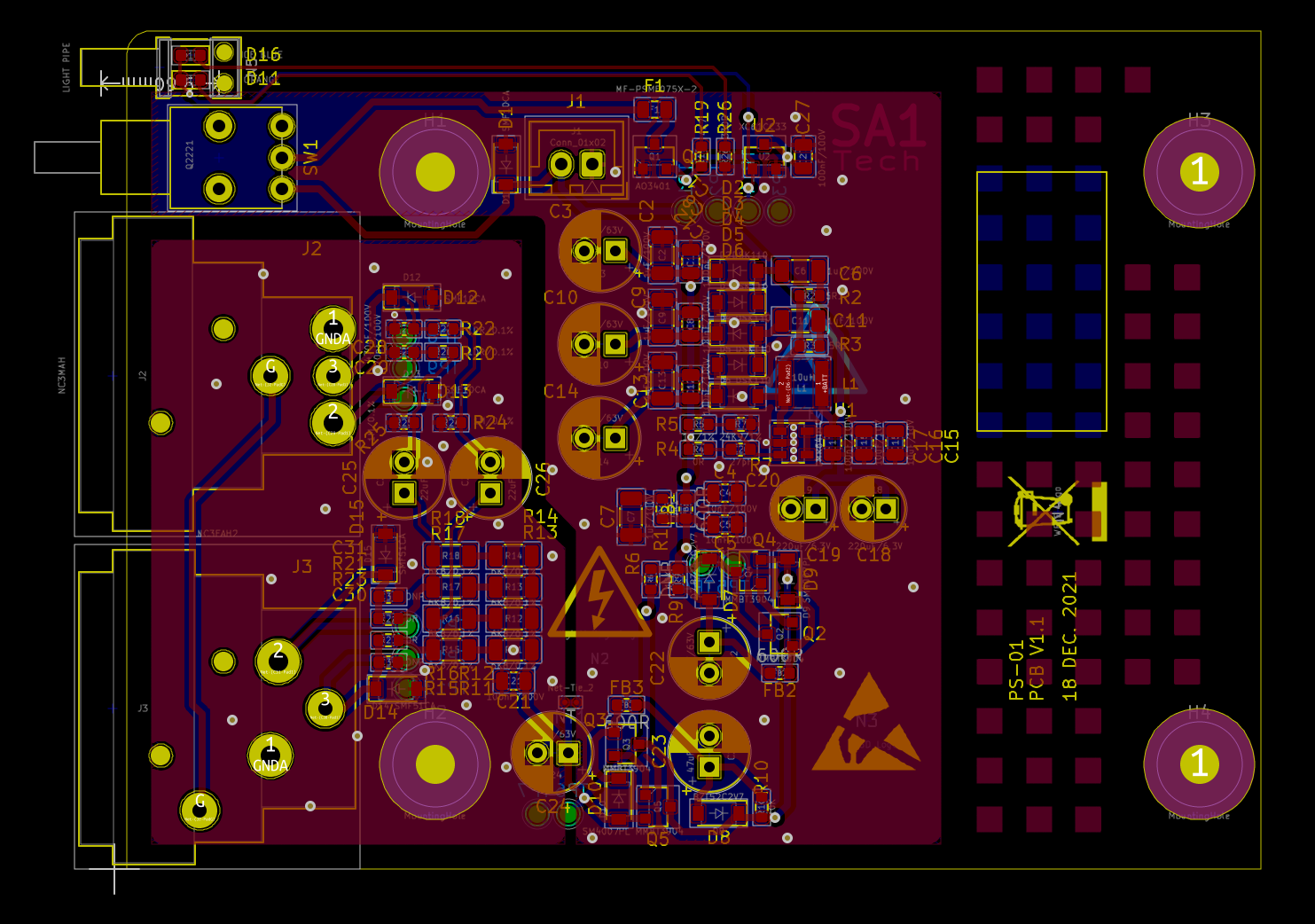
Schematic and PCB
Schematic and PCB were done with KiCAD 5.
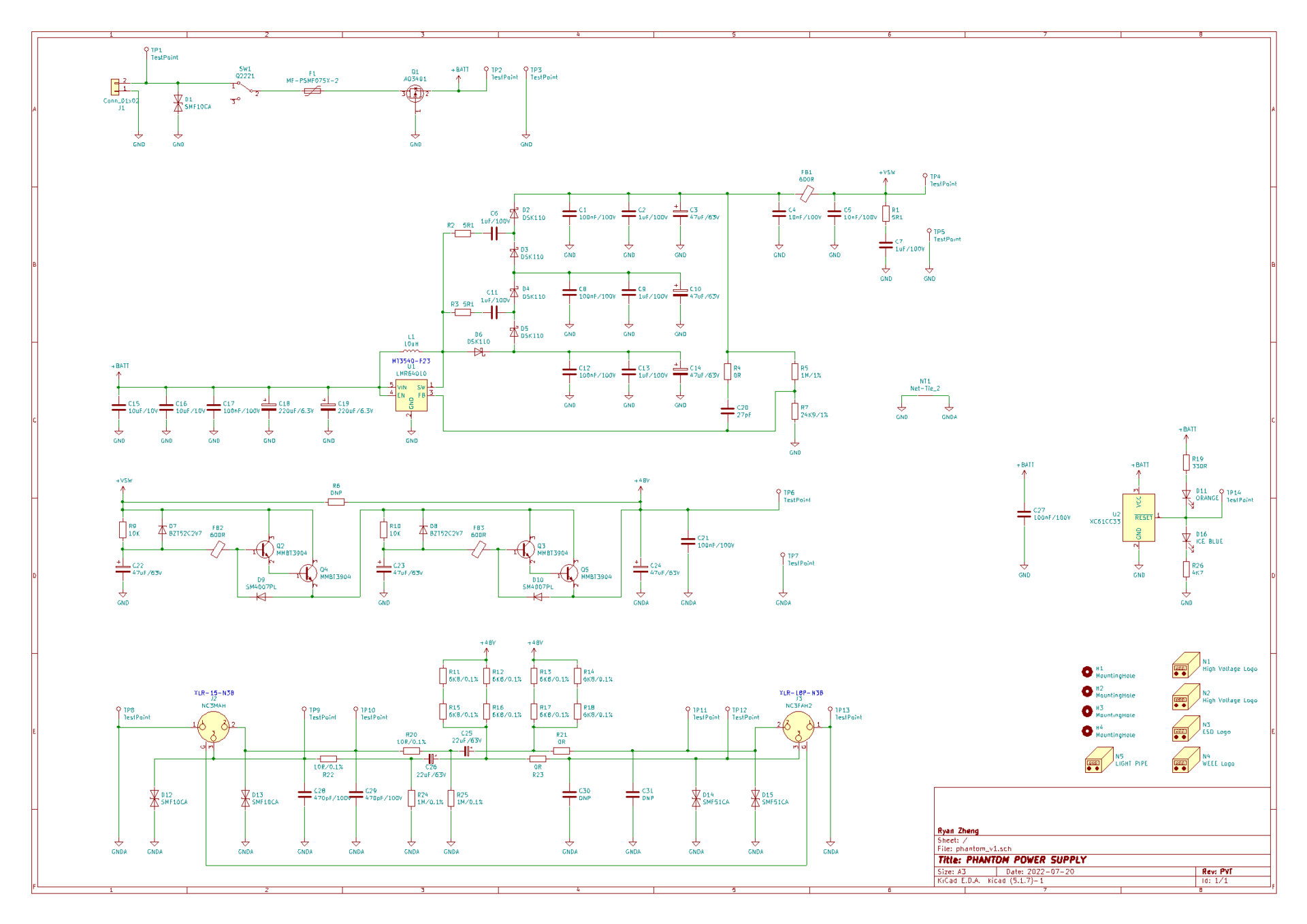
Circuit consists of a simple boost converter with added 3-stage diode voltage multiplier, a high voltage LDO, and a 2-stage Darlington capacitance multiplier for lowest noise possible. Protection circuitry and battery voltage indication were also added. A P-MOS blocks reverse battery, followed by a PPTC resettable fuse and transient suppression.
PCB is a normal 1.6mm 2-layer PCB.
Mechanical Design
Enclosure design was done with Solidworks 2018. STEP and STL files are also provided in the mech folder. The design is mostly complete, and should be injection-molding ready, with no draft angle in design file.
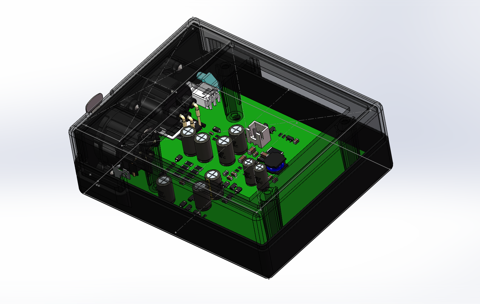
The PCB is held down to the base part by boss from top part, which are held together by self-tapping screws. The holes in the bosses are through, which are also used to mount the battery holder. The front panel is held in place by groves on both large parts. The battery holder is an off-the-shelf one which can be bought on Taobao or AliExpress. XLR connectors are fixed to front panel with self-tapping screws.
Make Your Own
You can fabricate the PCB and have it partly assembled by a PCB fab such as PCBWay(JDB PCB) or JLC-PCB. Solder only the common SMT parts at the fab, which I found to be the most cost-saving. A gerber file set is included in the output folder in the hardware design files. Other parts can be sourced from LCSC or another distributor. Hand soldering is mostly easy except the VSSOP LDO may be a little bit annoying. Alternative part number may be found in schematic.
Enclosure can be 3D-printed either at home or by a professional service. For FDM 3D-printing, remove small details that are not printable. Print top part upside down with support.
A BOM for assembling can be found under the docs folder. A interactive BOM for the pcb can be found in the ibom folder under the docs folder.
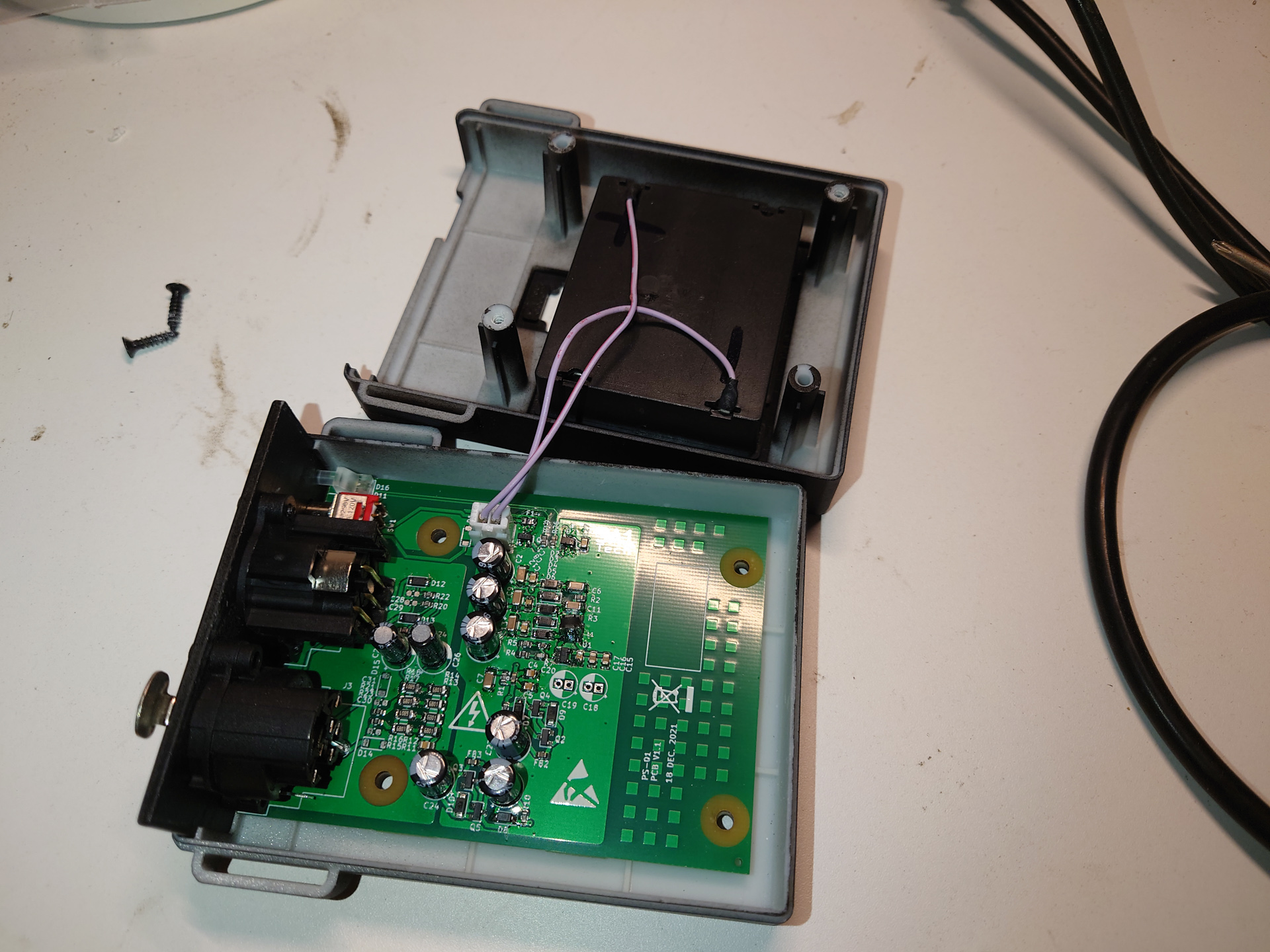
Assembling
- Push light pipe onto PCB
- Mount front panel to XLR connectors with 4 ST2.9×8 screws
- Solder XH2.54 pigtail to battery holder
- Mount battery holder onto top part of box with 4 ST3x10 screws
- Place PCB and front panel into base part
- Plug in battery XH2.54 plug
- Screw top and base part together with 4 ST3x12 screws
- Thread in hook-and-loop nylon cable tie