Table of Contents
- Overview
- 功放板维修 / Amp Unit Repair
- 箱体维修 / Cabinet repair
- 喇叭单元维修 / Speaker Driver Repair
- 组装 / Reassembling
- 使用体验 / Experience Using the Speakers
Overview
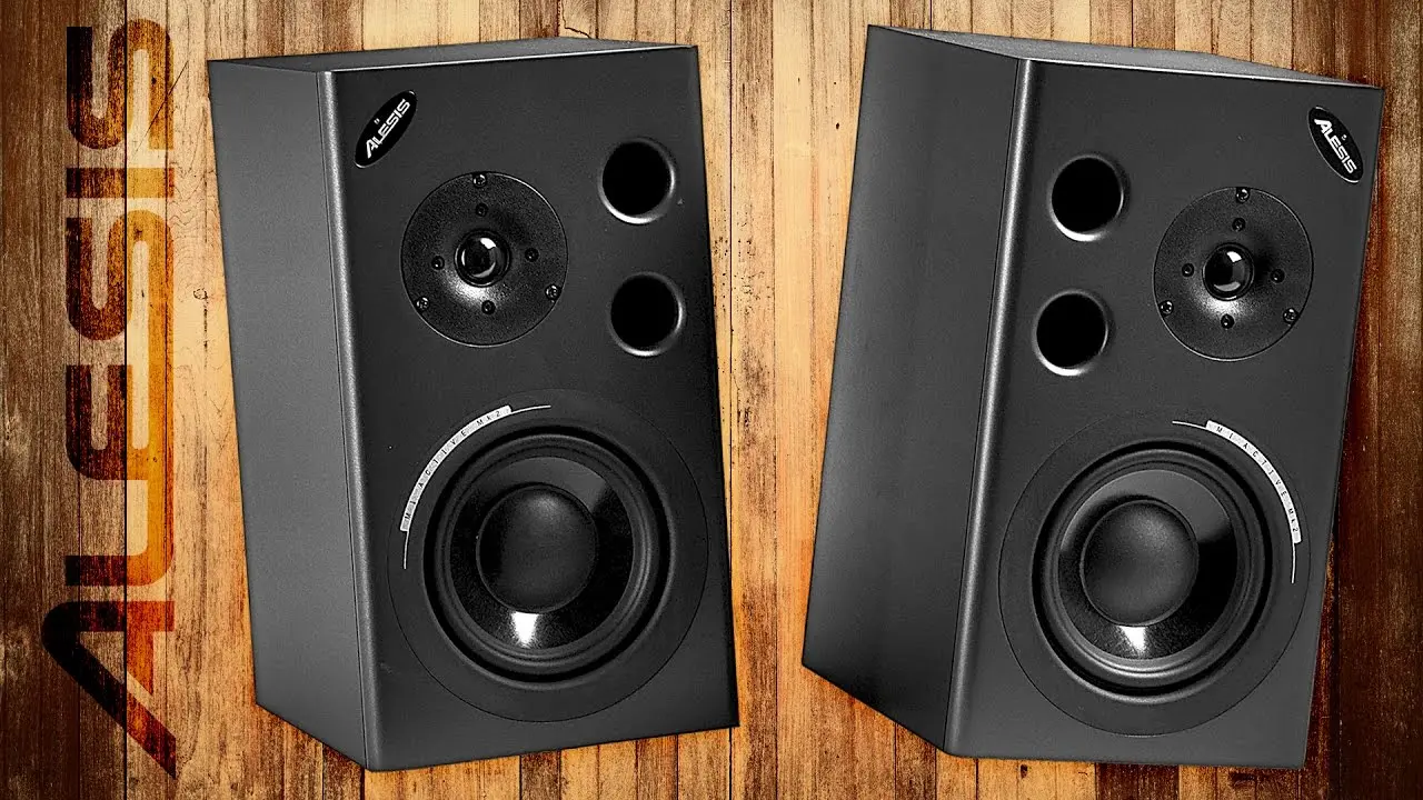
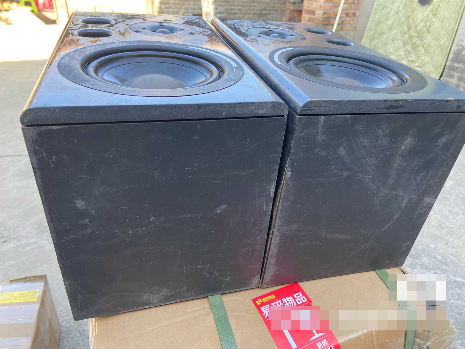
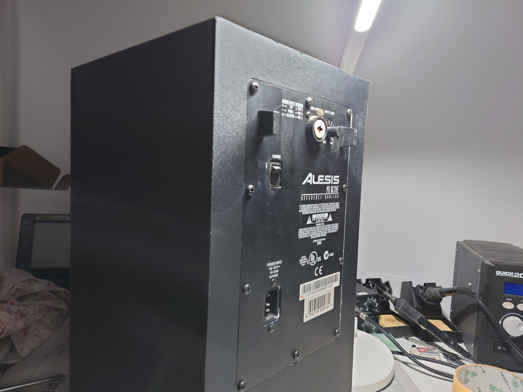
最近花400元收了一对有问题的Alesis M1 Mk2有源监听音箱,这款音箱在2010年前后是很受欢迎的型号。不幸的是,因为电路板设计问题比较多,没有多少留存到现在了。
I recently acquired a pair of Alesis M1 Mk2 monitor speakers for about US$70. This was a very popular model around the 2010s. Unfortunately due to bad PCB designs there aren’t many left now.
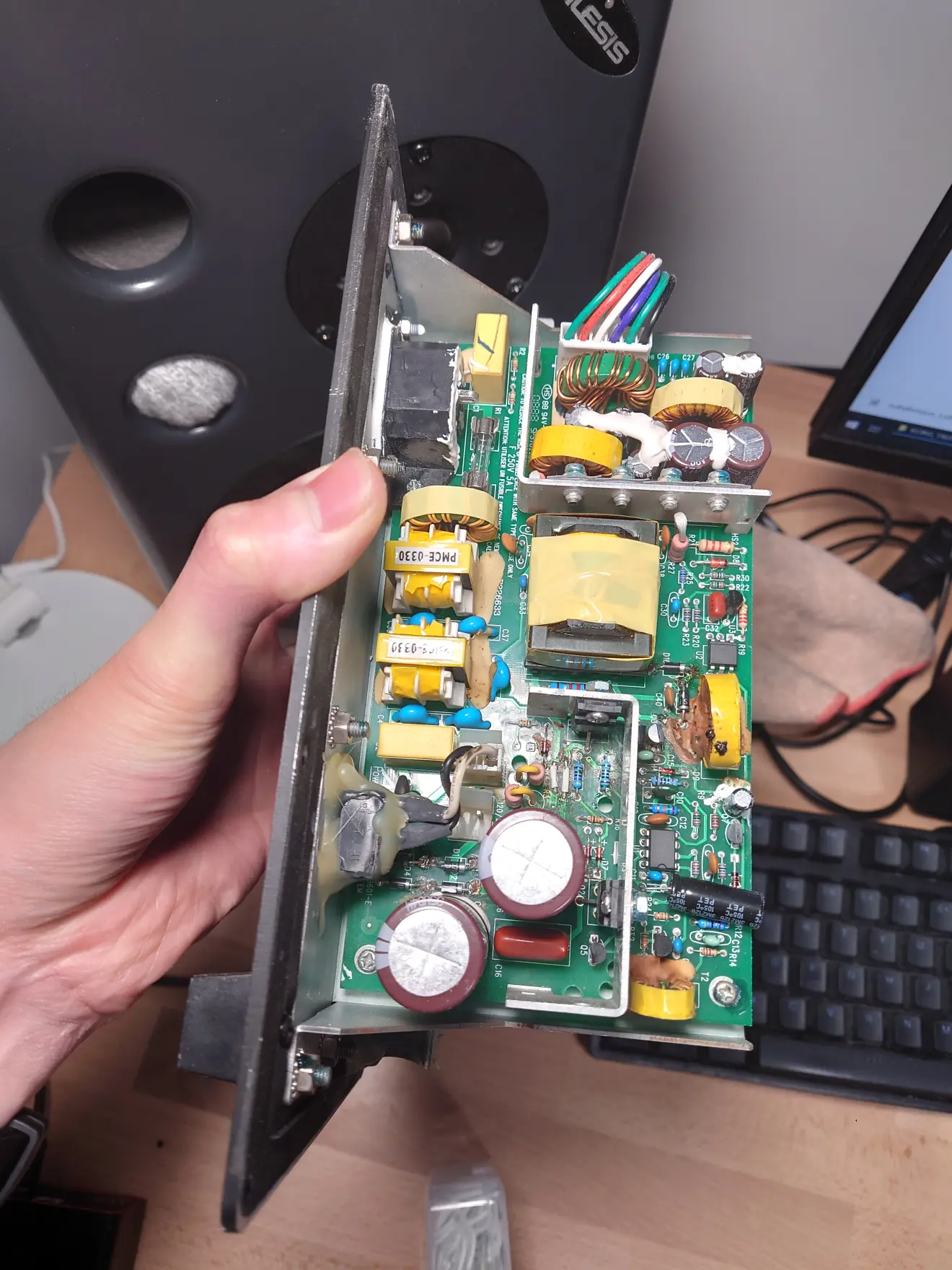
我收到的这一对2只音箱,拿到的时候有1只工作正常,另一只不上电。拆机检查后发现损坏情况:
The pair I got have one speaker working normally while the other one won’t power on. After tearing down I found the following faults:
| Part | One | The other one |
| Cabinet 箱体 | Normal 正常 | Water damage 泡水 |
| PSU Board 电源板 | Fried, with previous repair 损坏,曾经有维修 | Normal, with bulging caps 正常,电容鼓包 |
| Tweeters 高音单元 | dried up ferrofluid 磁液干了 | dried up ferrofluid 磁液干了 |
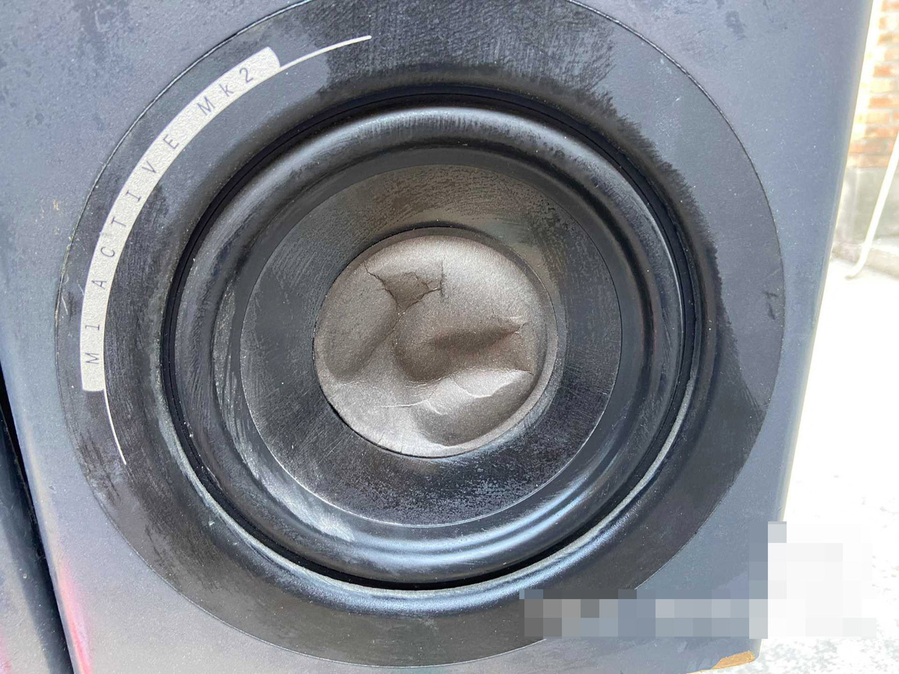
| Woofers 低音单元 | Normal 正常 | Pushed in dust cap 防尘帽凹陷 |
所以维修包括了电路板、单元以及箱体三个部分。实际工作量比我想象中大了不少,由于基本只有周末处理这个工作,整个项目持续了一个多月的时间。
Repair can be split into 3 parts: PCBs, drivers and cabinets. It was a lot more work than I imagined, and due to I only work on this project during weekend it took more than a month to finish all of the work.
功放板维修 / Amp Unit Repair
问题诊断 / Diagnosing

在badcaps论坛上有一个20页长的置顶帖子(https://www.badcaps.net/forum/showthread.php?t=10910),全部都是关于维修这款音箱的电器部分的,提供了很多非常有用的信息。根据网络上的信息、维修手册以及检查测量,发现如下问题:
There is a 20-page long sticky thread on the badcaps forum (https://www.badcaps.net/forum/showthread.php?t=10910) about repairing the electronics of this speaker, which provided a lot of useful information. Based on these knowledge, service manual, and inspection and measurements, I discovered following problems in the non-working PSU board:
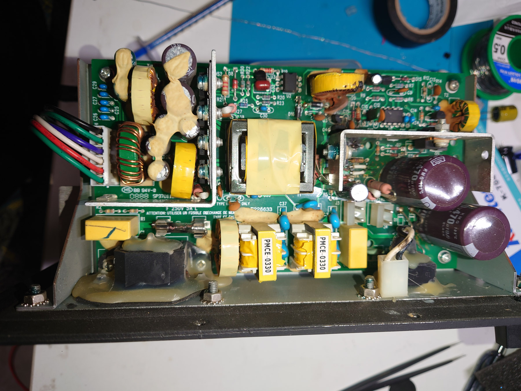
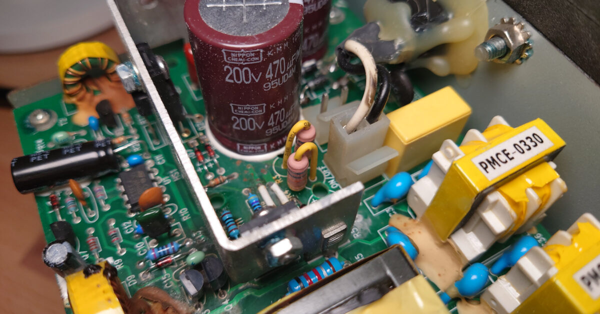
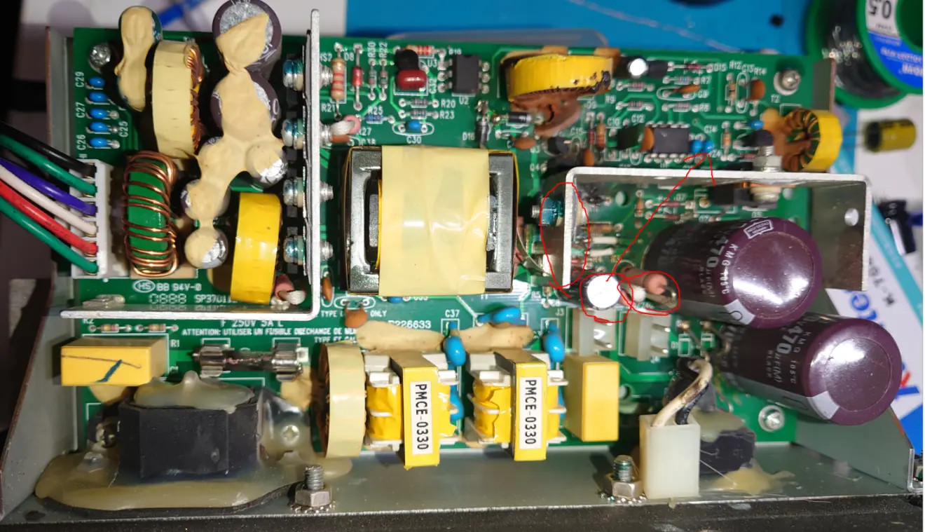
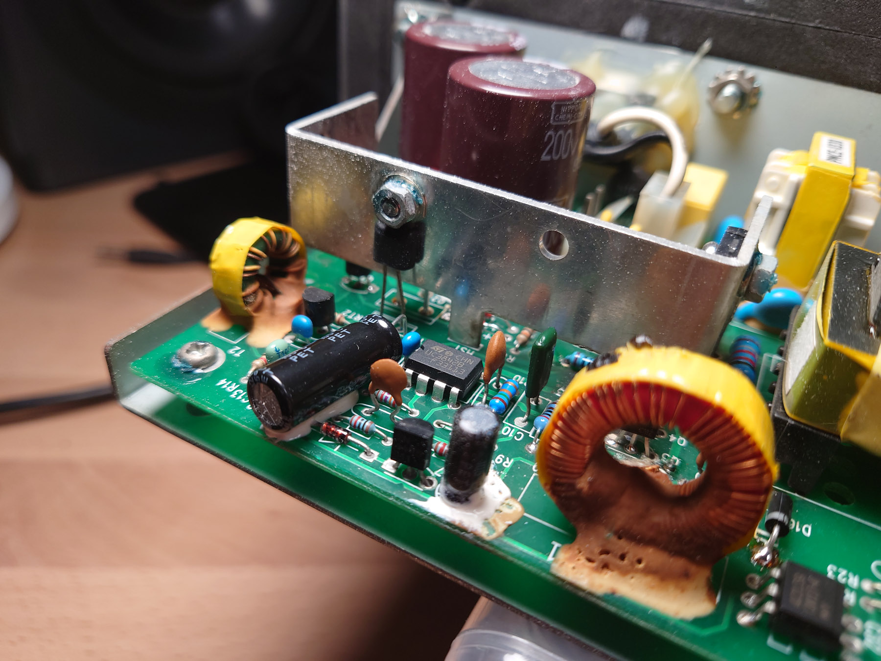
最明显的是R11已经烧糊了,说明Q1 S极有从主边滤波电容来的高电压(Q1 GDS全部短路,测量证实)。这个高压烧毁了采样电阻R15之后,烧毁R11。因此R10可能也有损坏。高压通过Q1 G极,烧毁Q3(Q3炸了)、Q4,因此C15、D9、R13、R12、C13可能也有损坏。去往光耦的线路有过流痕迹,但是没烧断,说明高压也去到了VCC网络,因此U1必然已经挂了,光耦也大概率损坏。
The most obvious fault was that R11 was obliterated, which means high voltage from mains filtering caps was present on source pin of Q1 (Q1’s GDS were all shorted together, confirmed by off-board measurements). This high voltage fried current sense resistor R15 before frying R11. Thus, R10 may also be damaged. The high voltage went through gate of Q1, fried Q4 and exploded Q3. C15 D9 R13 R12 may have also took damage. The silkscreen on the trace to the optocoupler were black suggesting over-current, which means high voltage was present on VCC network, so U1 must have been broken, alone with the optocoupler.
电路板维修 / PCB Repair
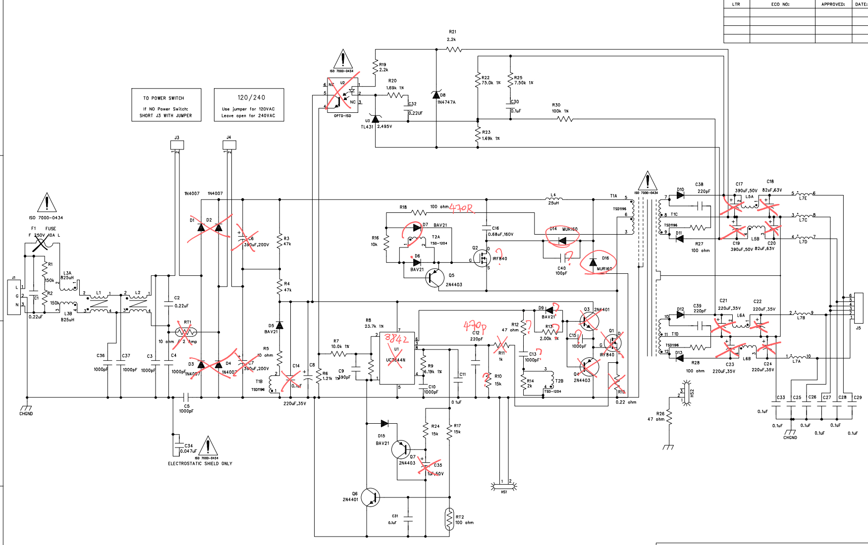
其他问题包括整流桥烧毁、NTC烧毁、D14 D16被替换成FR107(性能比要求的MUR160差很多)、电容鼓包。所以接下来移除所有可能有问题的原件,并进行检测。对于可能有损伤的原件(尤其是半导体器件)全部更换不保留。我在立创商城购买了原件。
由于UC3842已经停产,对比datasheet后,我选择使用新型号UC3842B进行替换。UC3842B启动电流比UC3842小,其他参数一致或更好,应该可以直接替换。
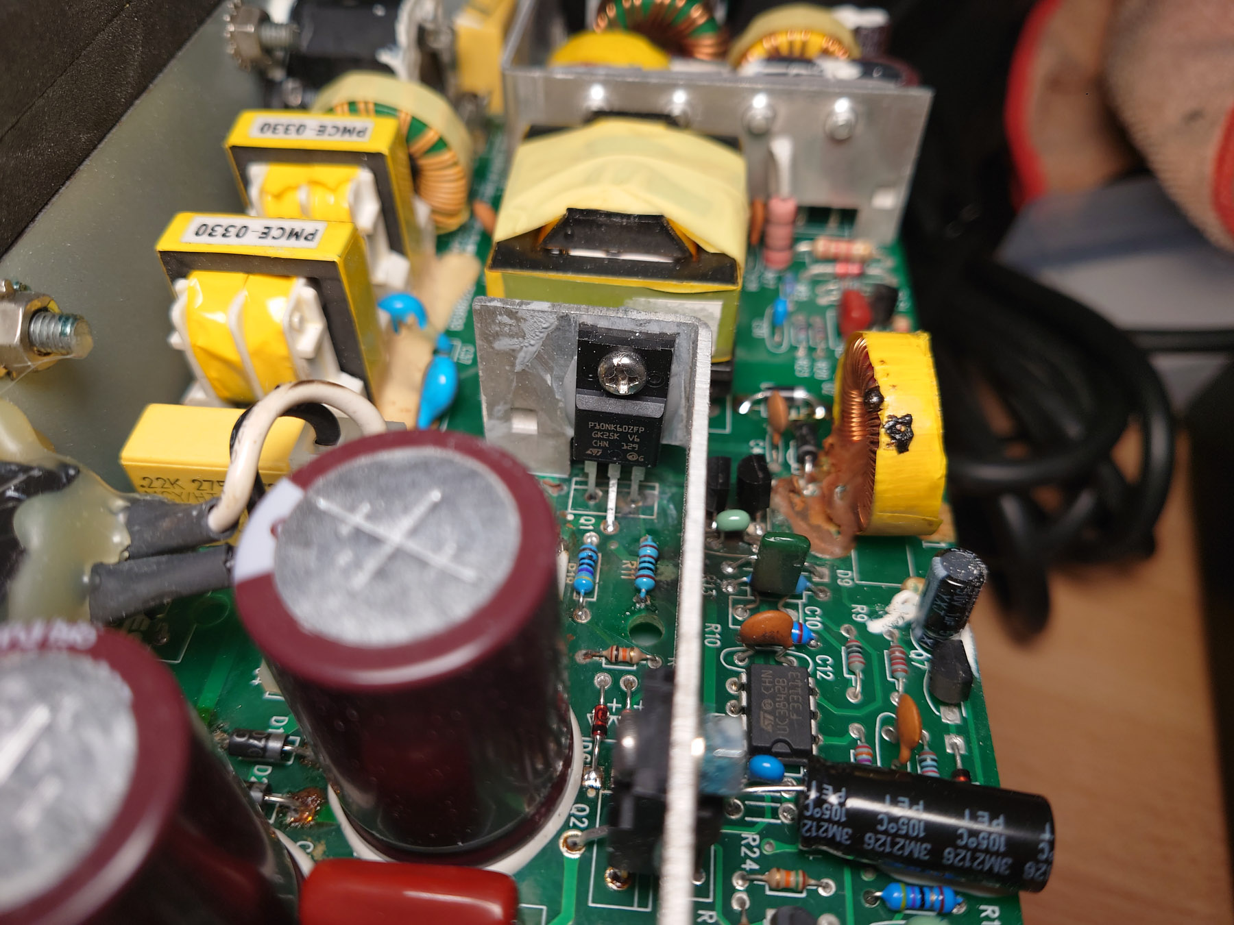
MOS管用ST的塑料封装600V 10A替换,D14 D16用SF18G 600V 35ns超快恢复二极管代替,光耦用CNY17-4替换。所有电解电容都换成了日本化工、红宝石或者尼吉康。
Other problems include fried 1N4007, exploded inrush limiting NTC, D14 D16 were replaced with FR107s which have poor performance, and bulging caps. So next step was to remove all offending components and test them. I also choose to replace any component that may have been damaged, especially semiconductors. I bought replacement parts from LCSC.
As UC3842 has been discontinued, I bought UC3842B by ST to replace the IC. UC3842B has smaller start-up current with other parameter being mostly identical or better, so there should be no problem using it.
MOSFETs were replaced with two 600V 10A ST MOSFETs in plastic TO-220 package. SF18G 600V 35ns ultrafast diodes were used for D14 D16. Optocoupler was replace with a CNY17-4. All electrolytic caps were replaced with either Chemi-Con, Rubycon or Nichicon ones.
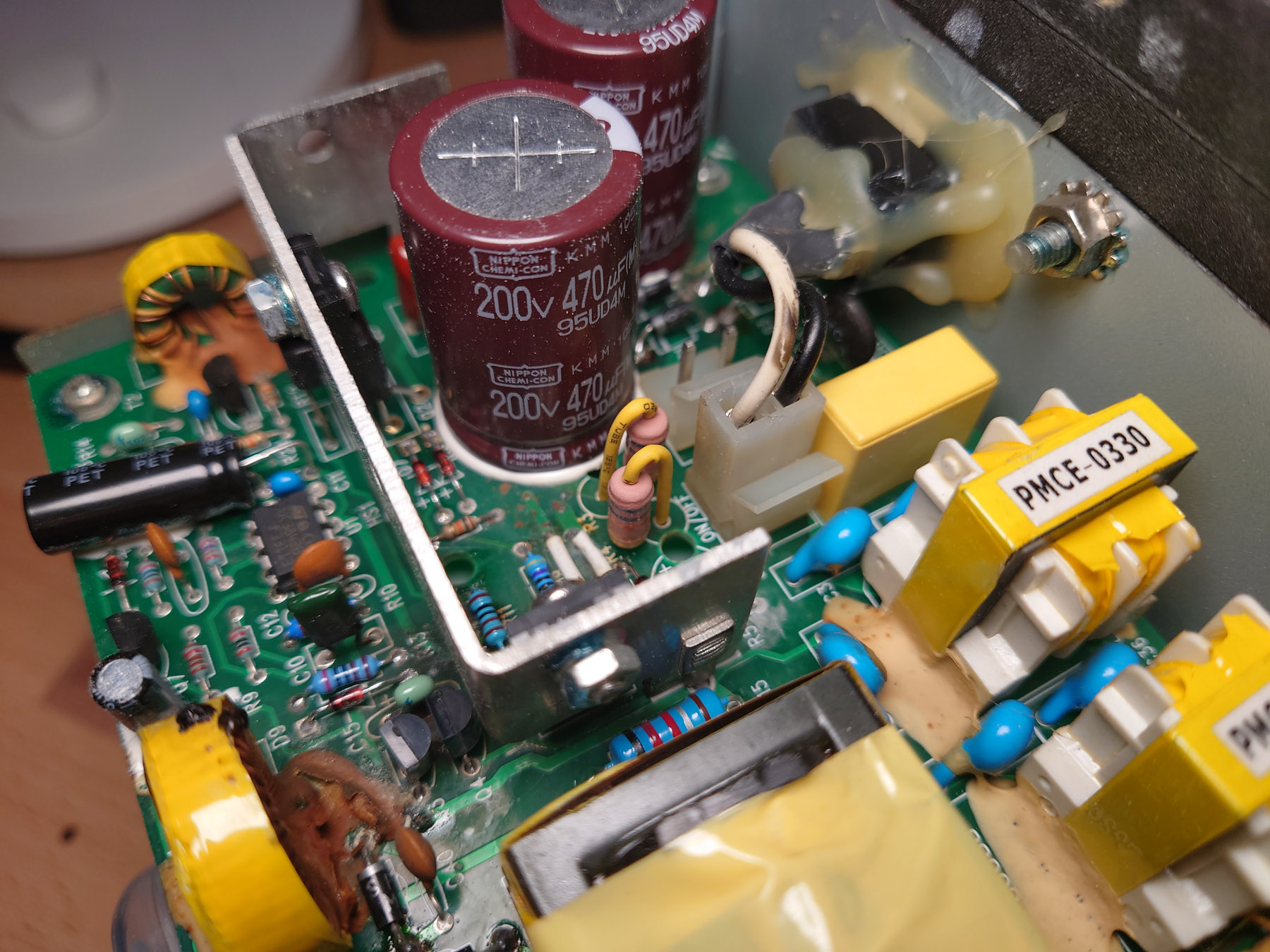
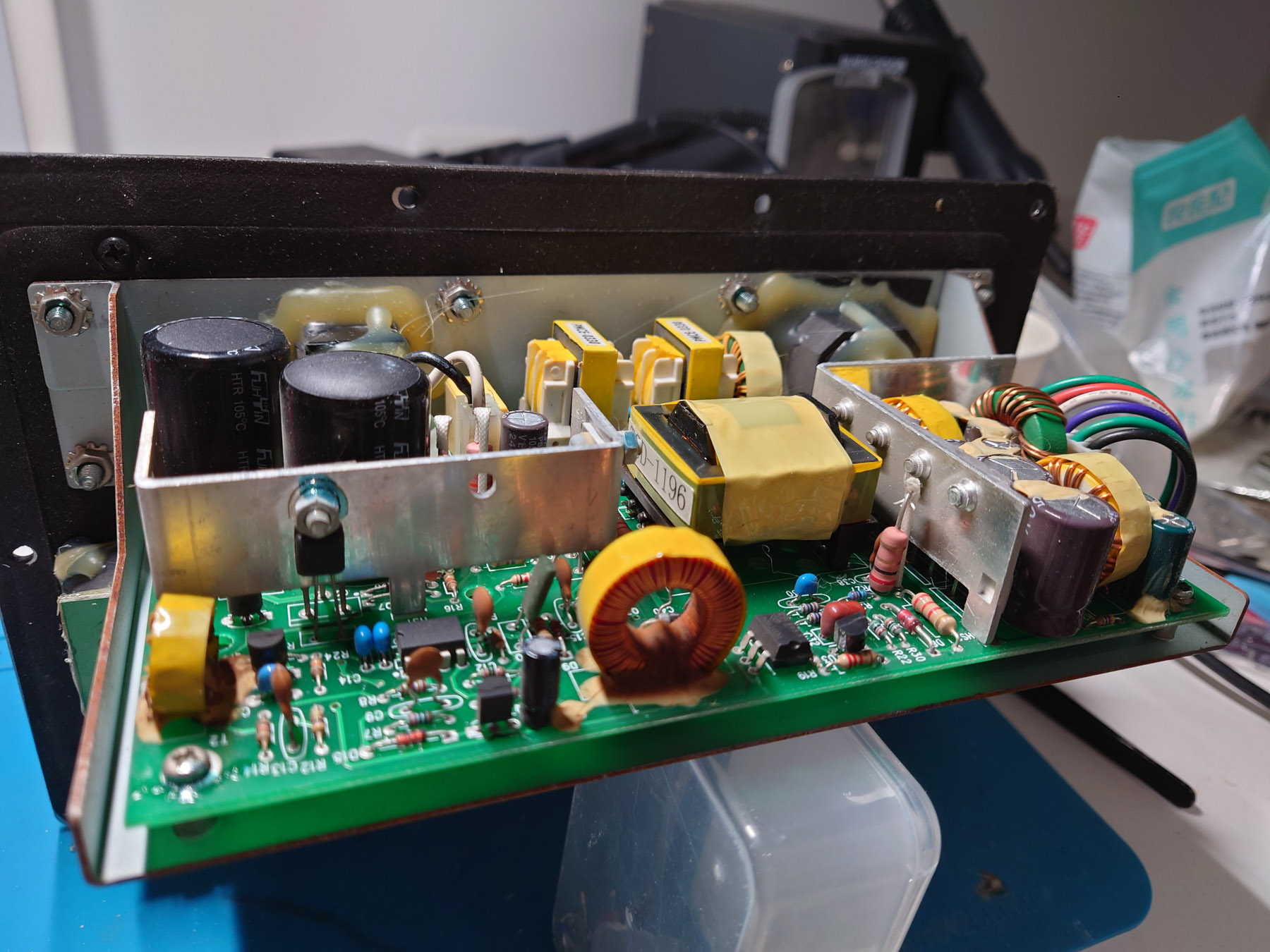
电源板容易烧毁的原因是R3 R4阻值较小,发热大而且离VCC滤波电容C8太近,开关管的散热片也在C8旁边,将C8烤坏。R3 R4是主滤波电容的泄放电阻、均压电阻以及启动时VCC电源的来源。启动时高压直流通过R3 R4向C8充电,当电压达到15V左右时,U1启动,一旦开始开关,VCC电源由辅助绕组T1B经过D5整流提供。
The reason the PSU board is prone to self-destroy is that R3 and R4 have relatively small value thus generate a lot of heat. They were placed close to VCC filtering cap C8, and switching transistor’s heatsink was close to C8 as well so they constantly bake C8 until it dies, taking out everything. R3 R4 serves as discharge resistor, voltage balance network and startup source. On powering up, high voltage DC charges C8 through R3 R4, when voltage on C8 reaches about 15V, U1 starts and once switching is established VCC is supplied by auxiliary winding T1B and rectifier D5.
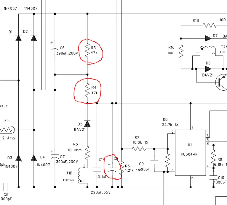
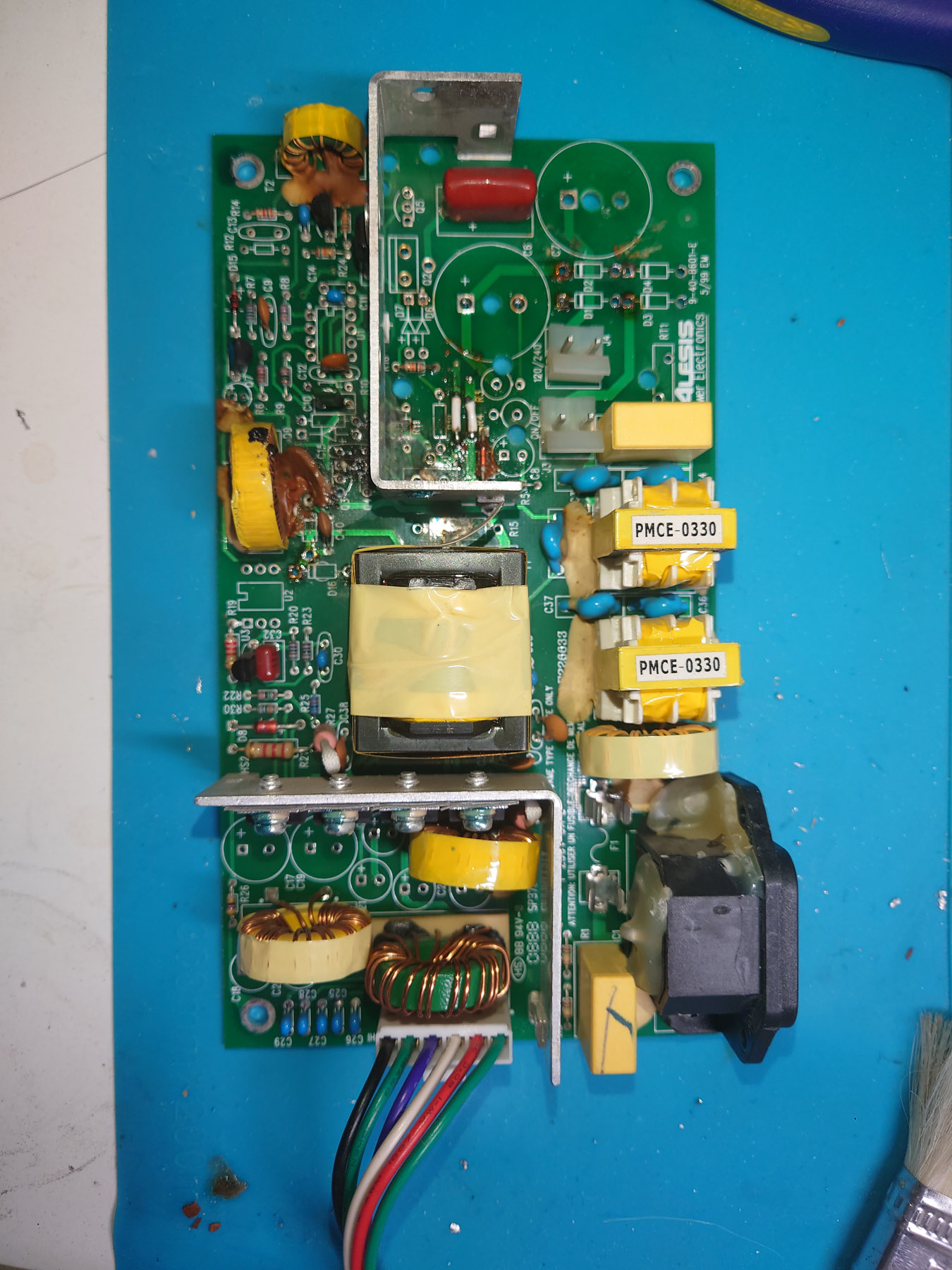
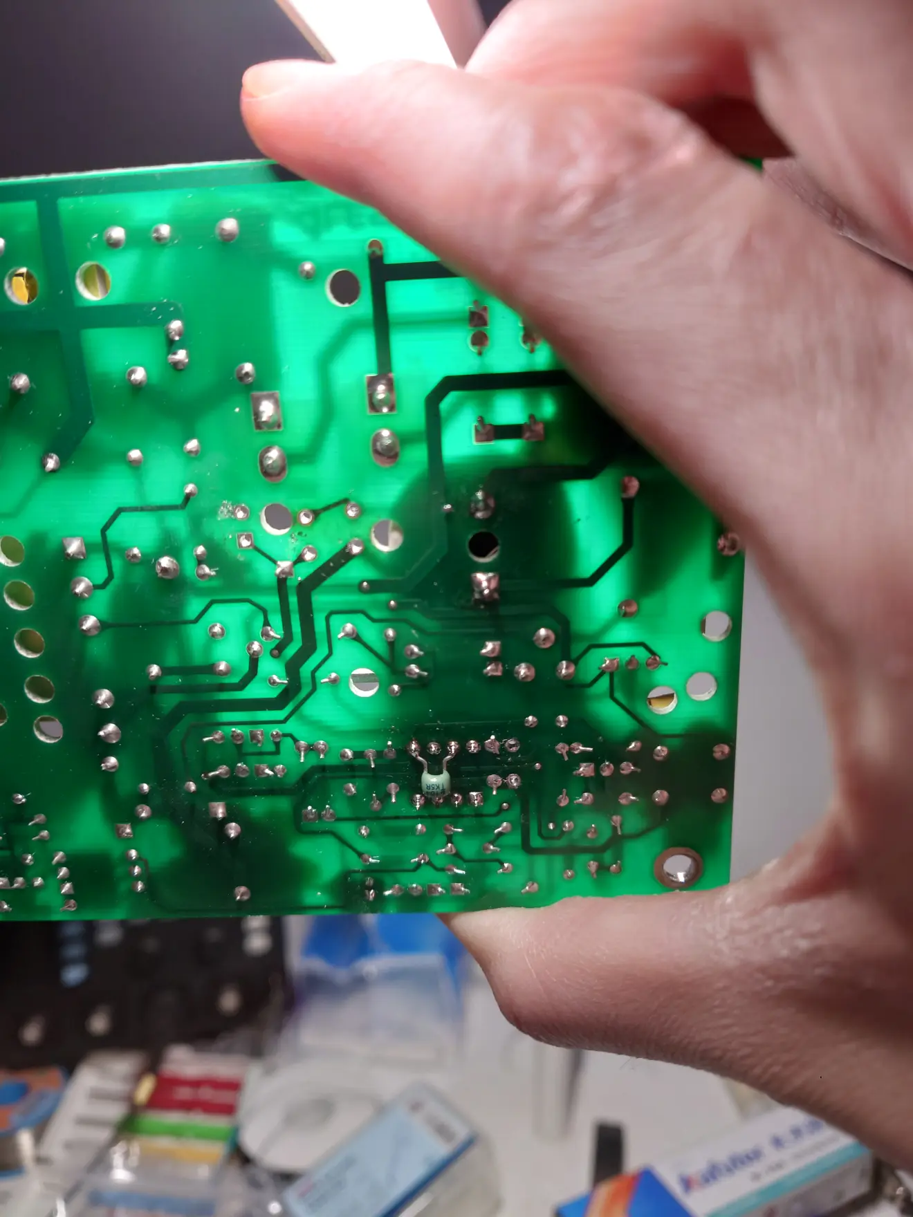
根据badcaps论坛上的帖子和我的分析,我将C8移动至C14的位置来远离热源,C14移动到板子背面。R3 R4增加到68K。这可以避免将来出现同样的问题。
Based on the Badcaps thread and some analysis, I decided to move C8 to C14 to keep it away from the hot spot, move C14 to bottom side of PCB and increase R3 R4 to 68K. This should avoid or at least delay the same problem from happening in the future.
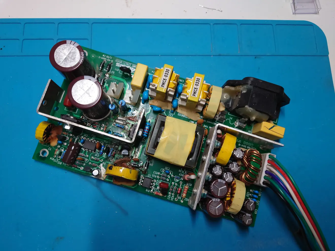
原件到了之后就是常规的焊接更换。可以看到C8被移动到了C14的位置。
After the parts arrived, I soldered everything on as usual. C8 can be seen at the location of C14.
测试电源板 Testing the PSU
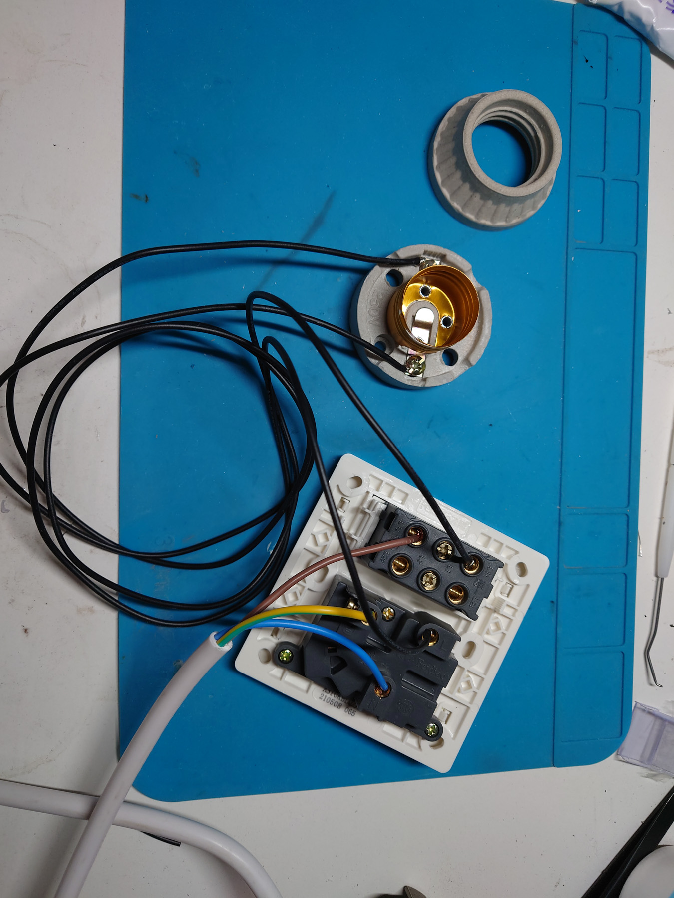
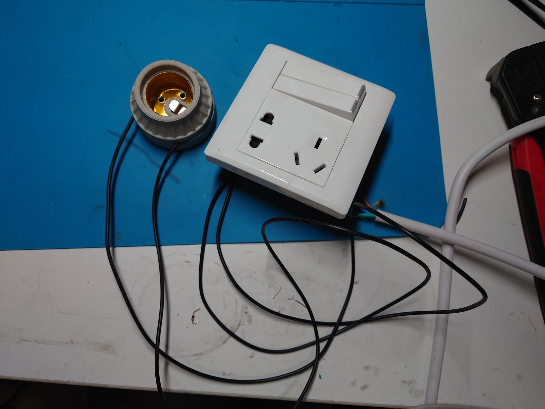
测试电源板时,为了防止更多损坏,以及爆炸伤害,我用串联灯泡的方式进行调试。一个100W的白炽灯泡被串联在220V线路中。这样,如果电源没有问题,上电的时候灯泡会亮一下,之后就不亮了。如果电源有短路,灯泡会一直亮,并且由于灯泡功率是100W,短路电流被限制为0.5A以下。
When testing the PSU, to avoid further damages and injuries to myself, I used the series-bulb method. A 100W incandescent light bulb was put in series between mains power and PSU. That way, if the PSU is fine, the bulb will light up briefly on plugging in the power, and remain off later. If there is a short circuit in the PSU, bulb will light up. As the power of the bulb is 100W it will limit the short-circuit current to below 0.5A.
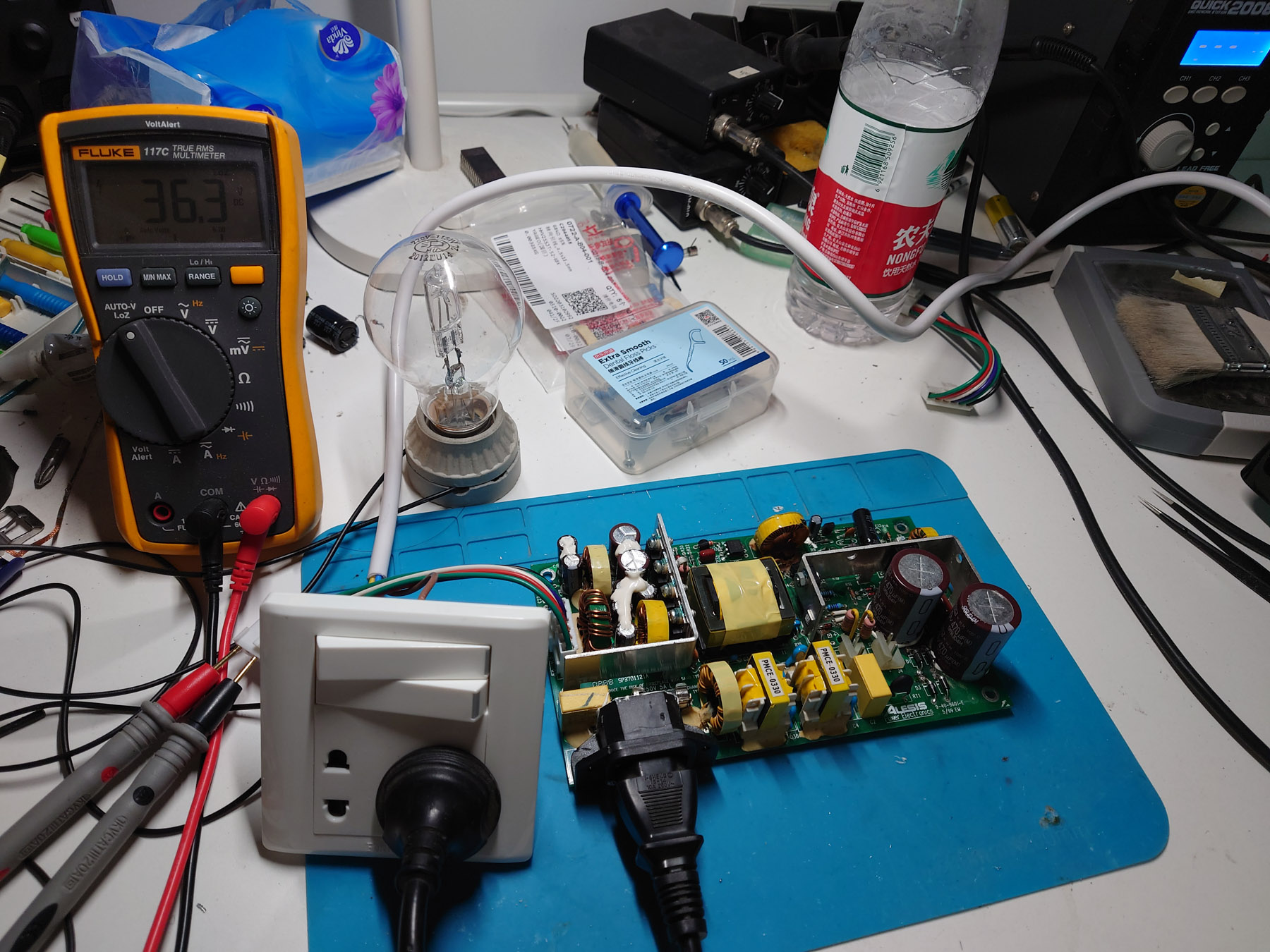
测试时我没有考虑到这个电源在空载时不稳定,所以导致走了很多弯路。挂上功放板后就没有问题了。
测试没有问题之后我将正常工作的那块电源板进行了更换电容,将R3 R4 U1 C8 C14也进行了相应的更改。
I didn’t know this PSU cannot run under no load, which created a lot of confusion for me. Luckily everything worked out after I hooked up the amplifier board.
After some testing I decided it is good enough so I performed the same change of R3 R4 U1 C8 C14 on the still working board, and replaced all electrolytic caps.
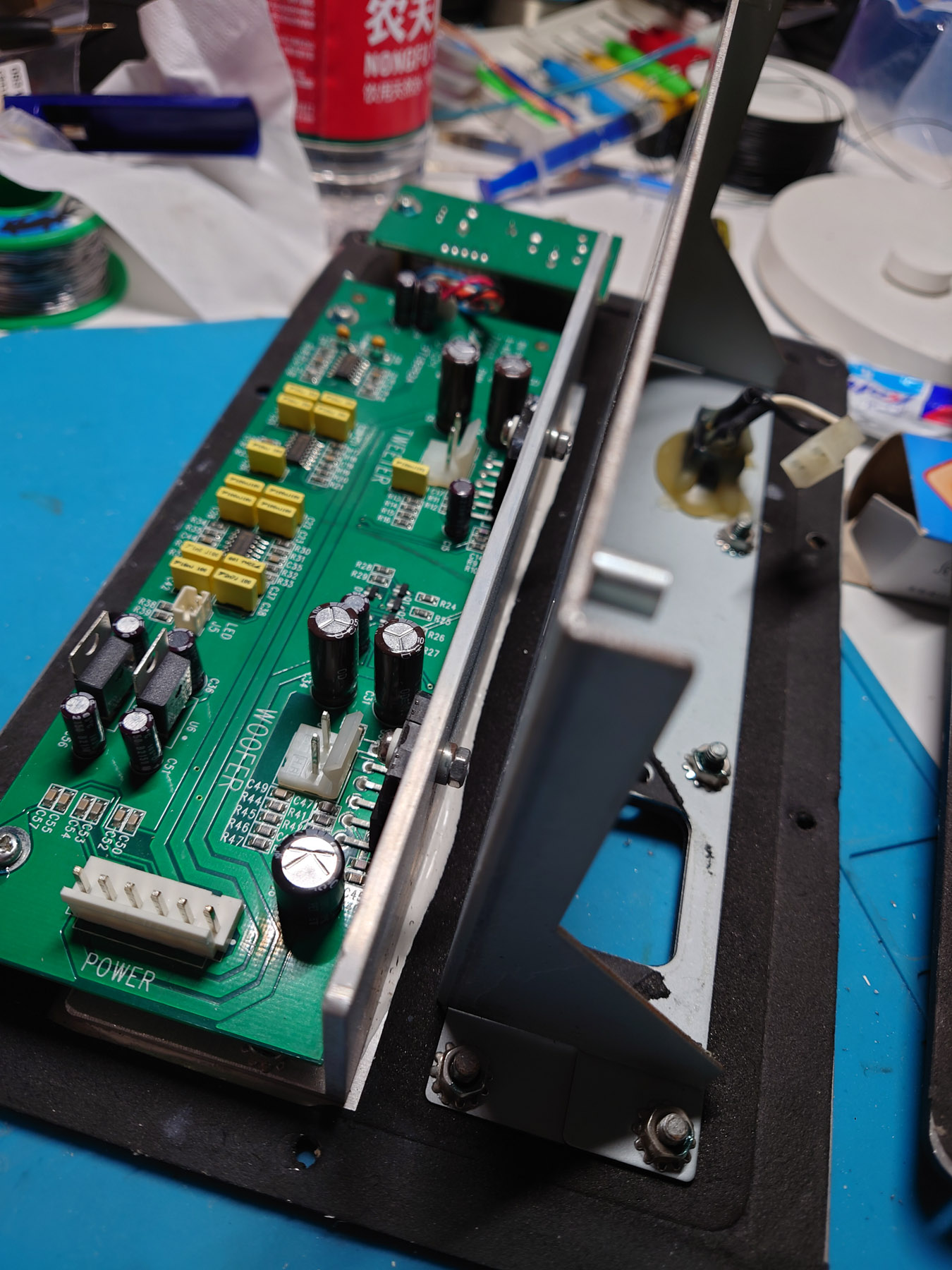
打理功放板 / Work on the Amp Board
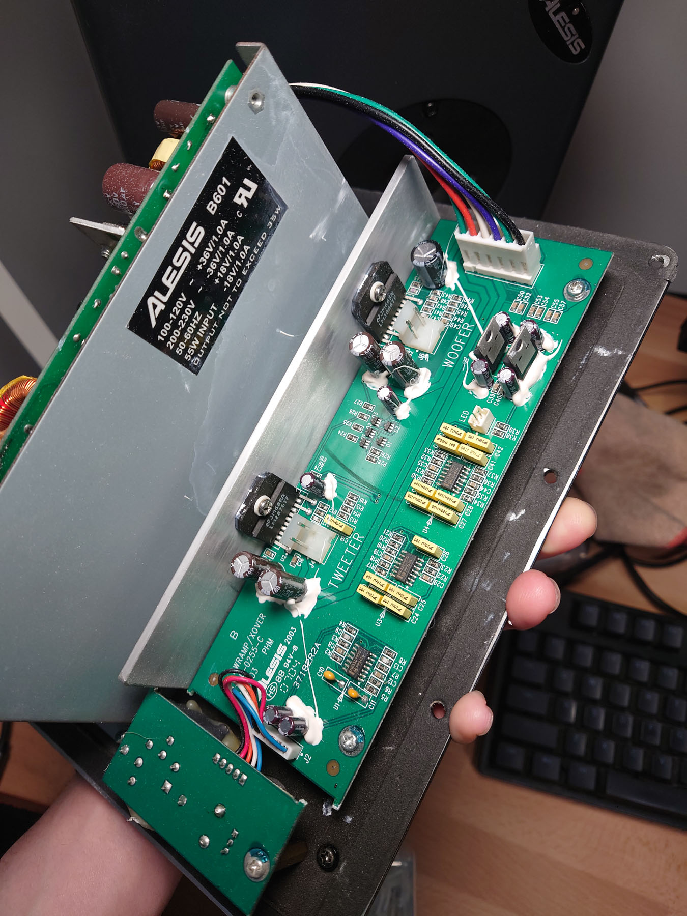
功放板上的所有电解电容也进行了更换。
All electrolytic caps on both of the amp boards were also replaced.
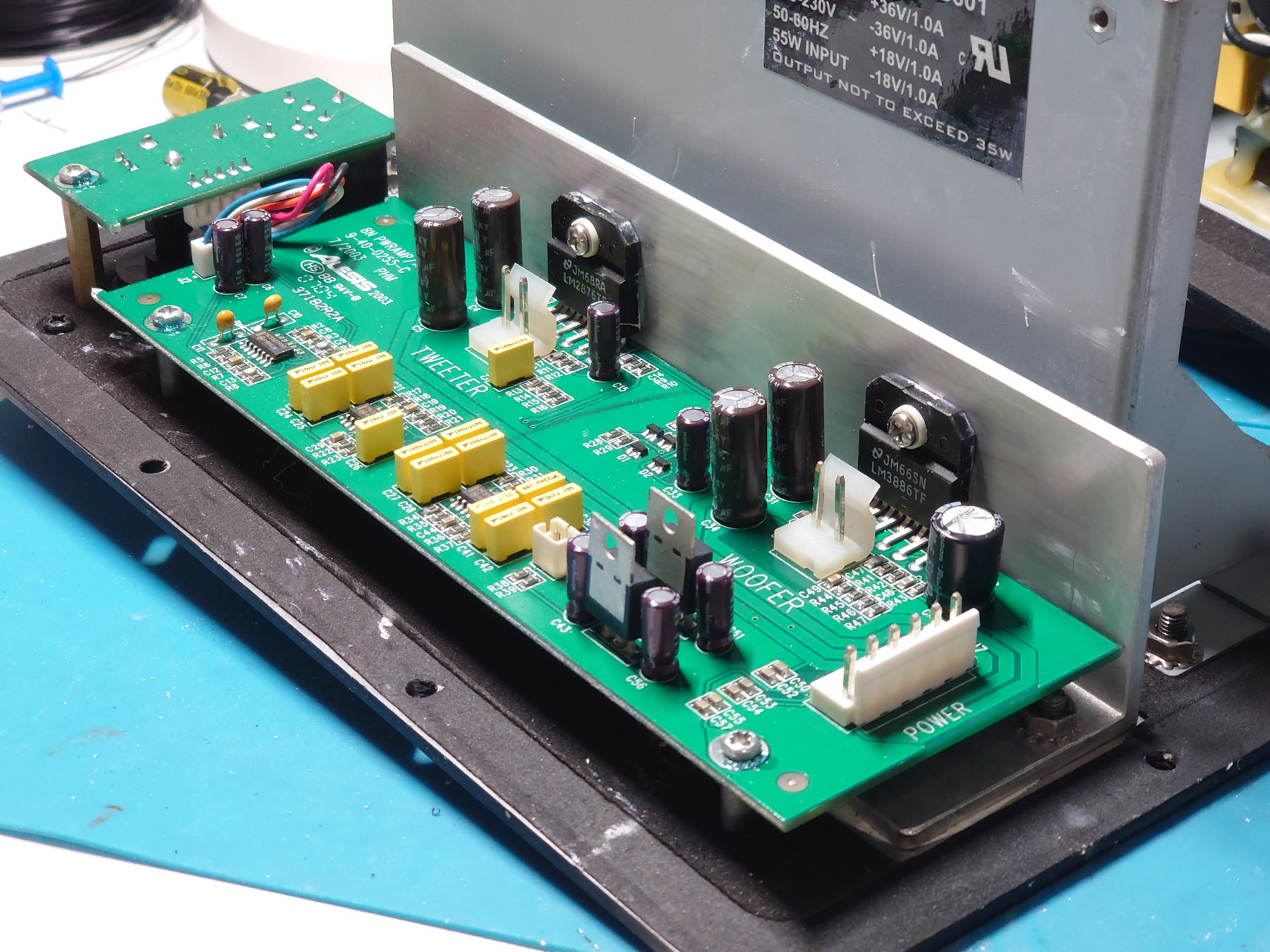
看过EEVBlog的视频之后,为了防止音频振动导致的损坏,所有大型原件都用704硅橡胶进行了加固。
I watched the EEVBlog video and didn’t want no component to be “flapping in the breeze”. So to prevent damage caused by vibration, I applied RTV silicone rubber to all large components.
功放组装 / Reassembling Amp Unit
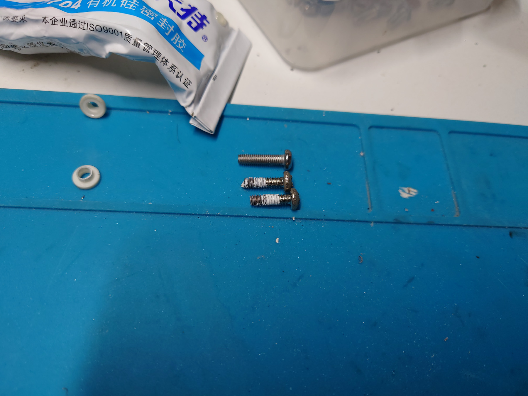
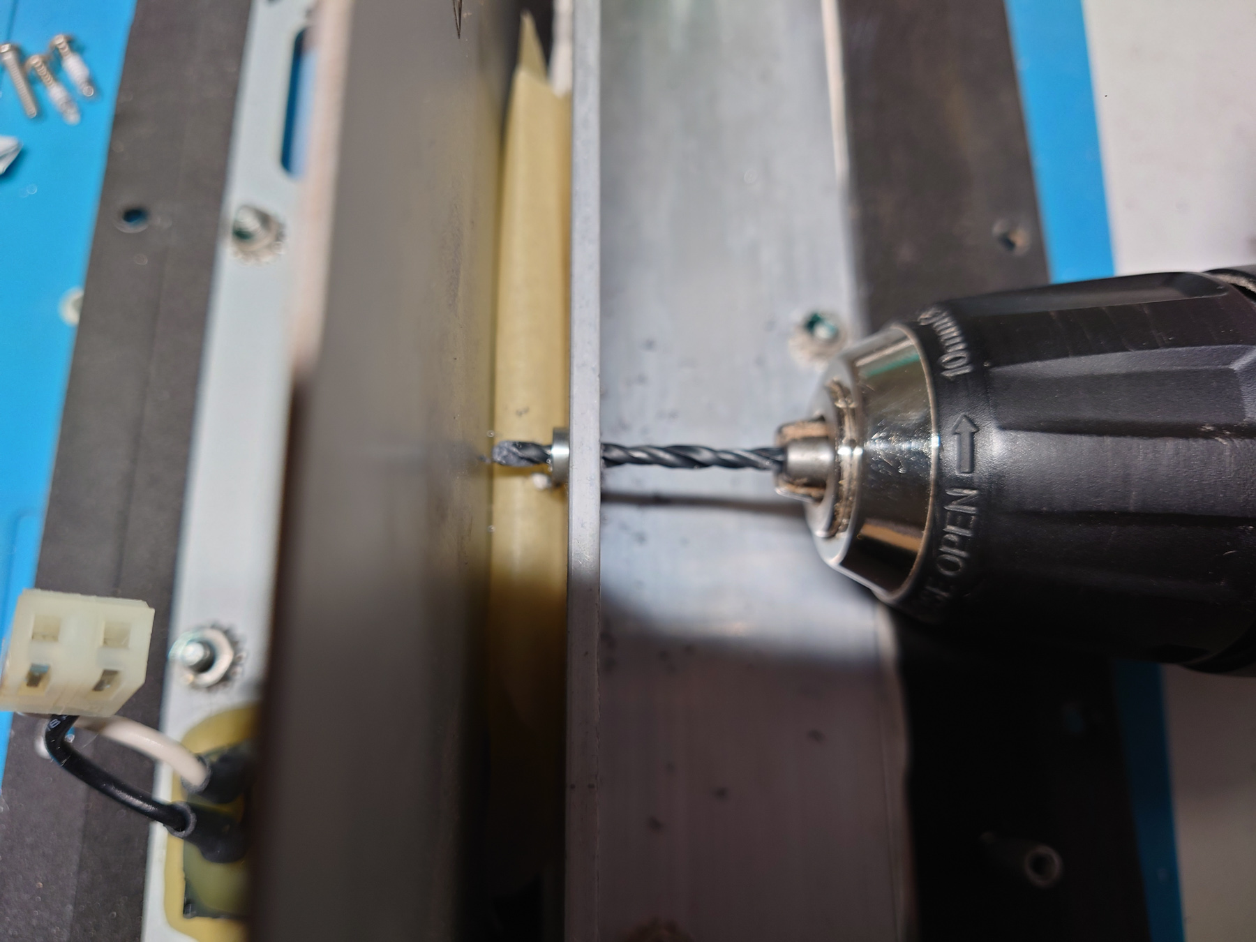
拆卸功放板的时候发现固定功放芯片的螺丝非常紧,怀疑是导热铝板上没有攻丝,直接拧入的。拆下的时候螺丝头全部损坏了,还把我的南旗批头搞坏了。回装的时候,我把原有的孔扩大为3mm,在导热板后面加了螺母,用M3螺丝固定。
When disassembling the amp I found that the screws holding the power amp IC were extremely tight, as if there were no threads on the aluminum board and they just screwed it in by force. All 4 screw heads were badly damaged, and it even managed to bite out one of my screwdriver bit. When installing it back in, I drilled the hole to 3mm and used M3 screw with nut to hold the amp IC.
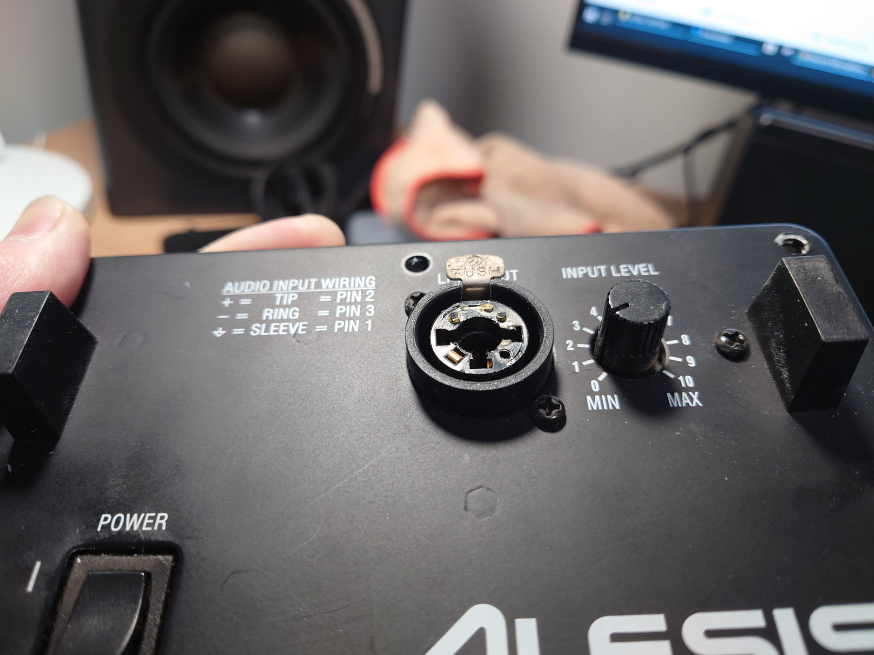
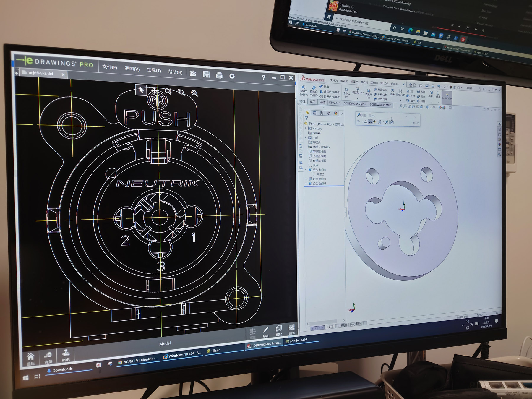
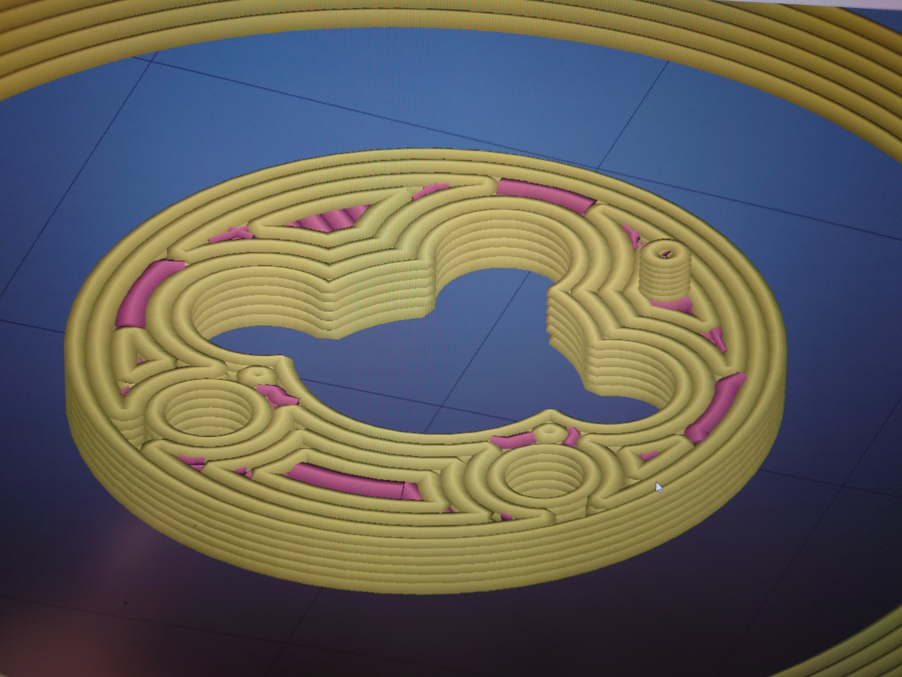
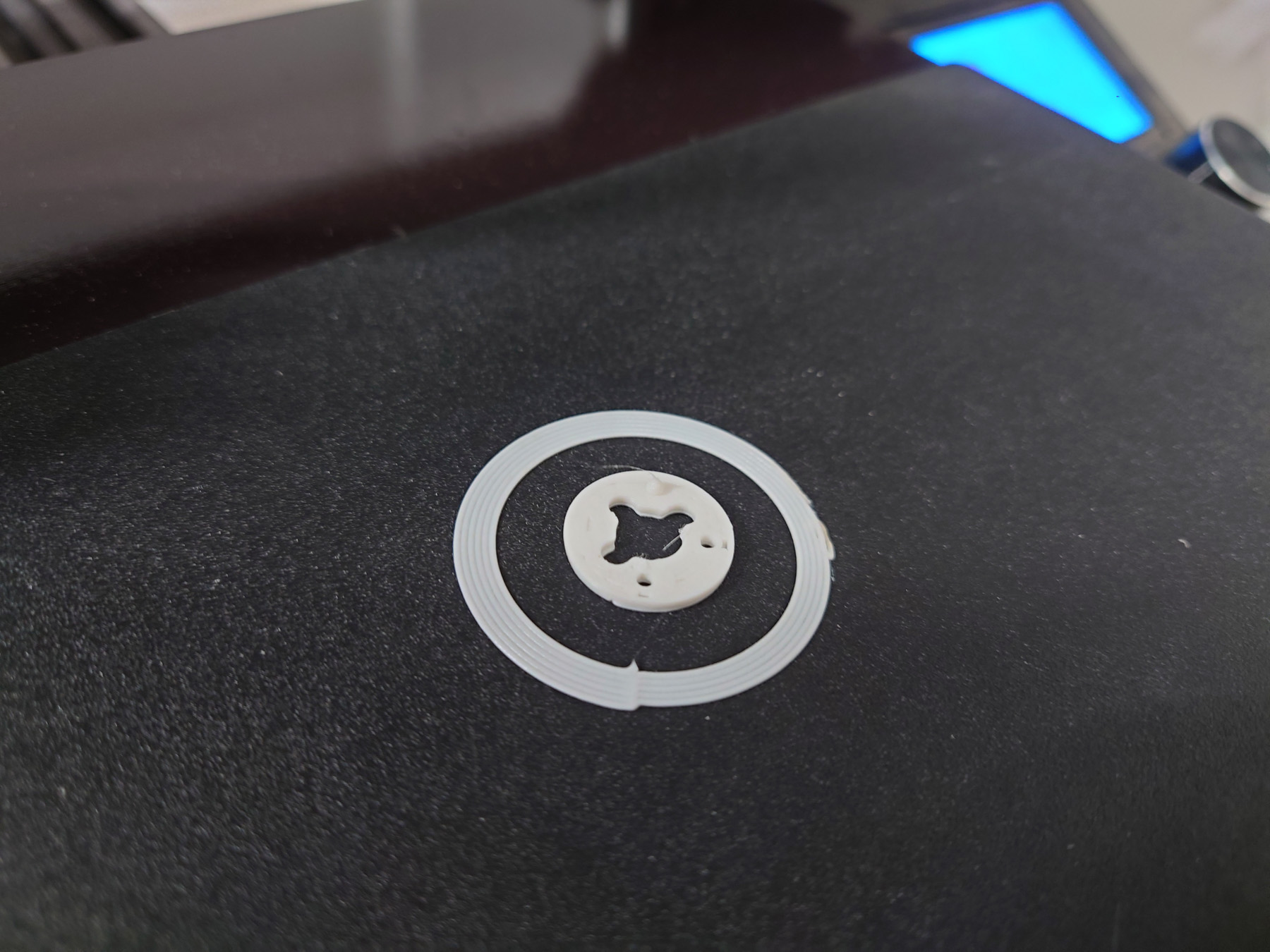
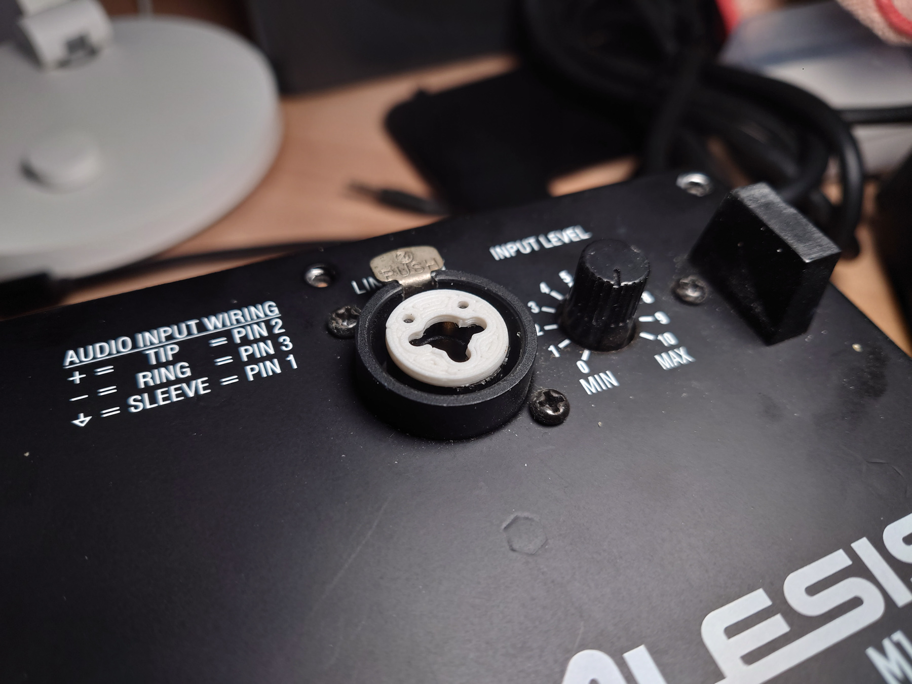
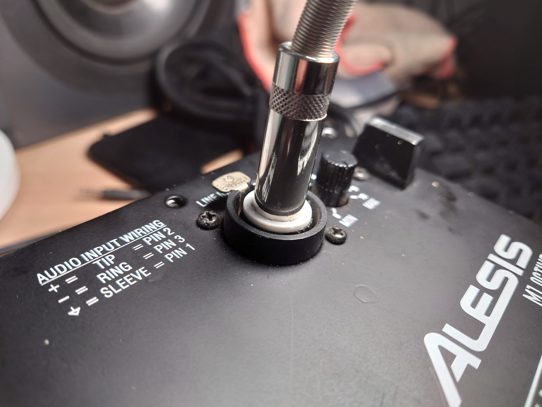
修理XLR连接器 / Repair XLR Connector
一个功放板的XLR输入连接器缺少一个面板,我画了一个,3D打印出来,并用强力胶粘上。
One of the amp is missing a plate on the XLR connector, I designed one, printed with my Ender-3 3D-printer and superglued it in place.
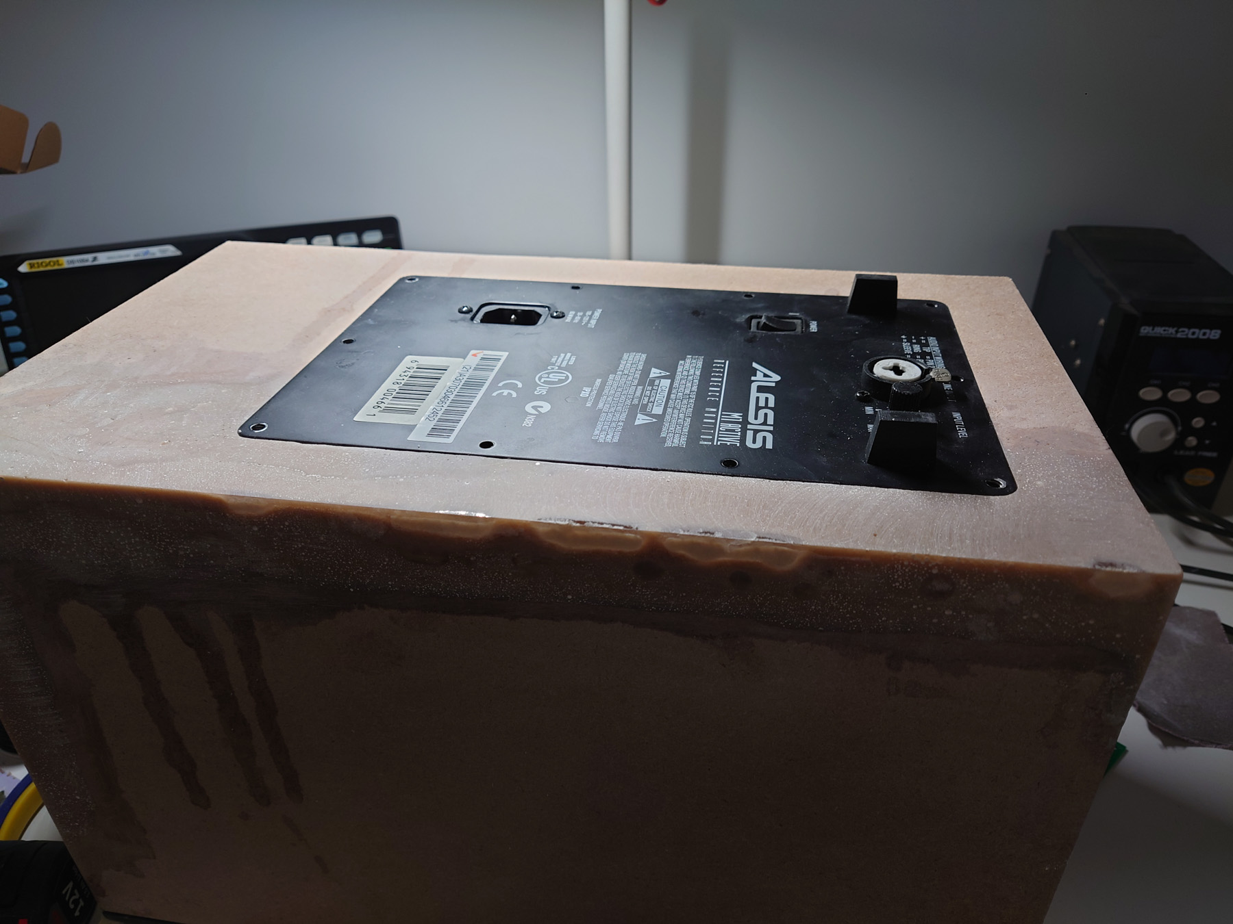
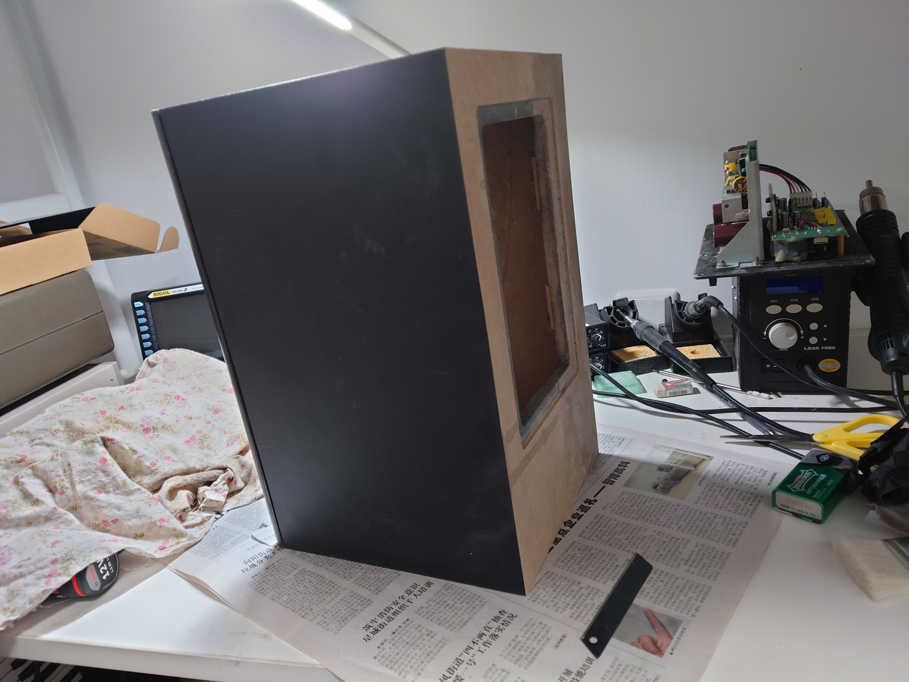
箱体维修 / Cabinet repair
一只箱体受到了水浸损坏,还好内部接缝并没有裂开。我先用旋转锉移除所有松散的木头。
One cabinet suffered water damage, luckily the seam on the inside is still intact. I first remove all loose MDF that has been soaked.
用环氧树脂稳定界面
Stabilize the surface with epoxy
3D打印背板来辅助重做外形
I 3D printed a mock back panel to help with reconstruction
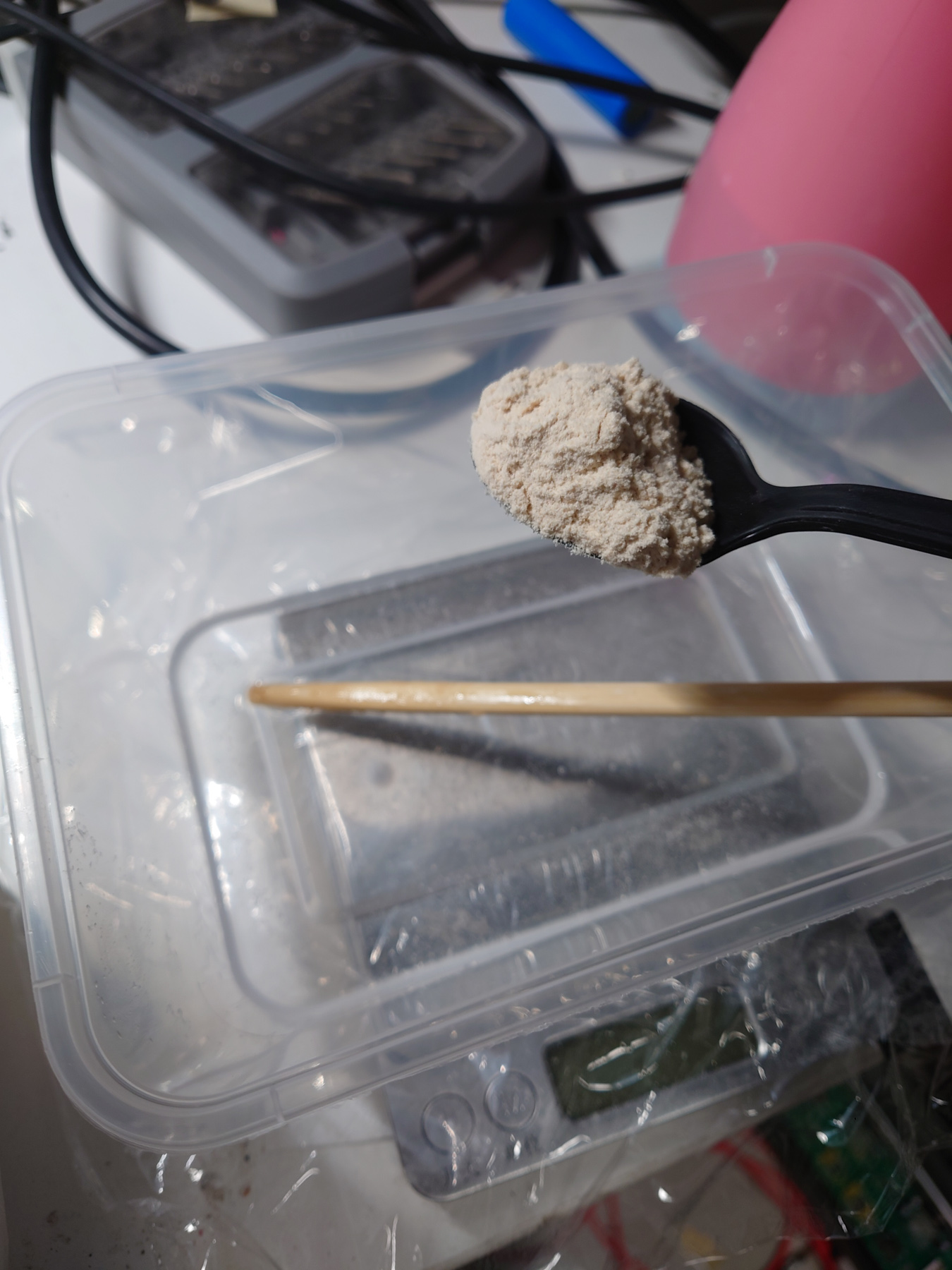
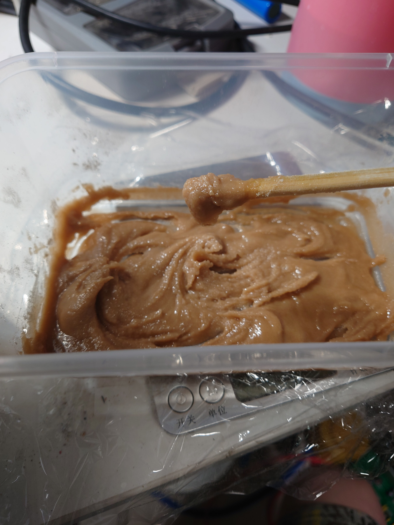
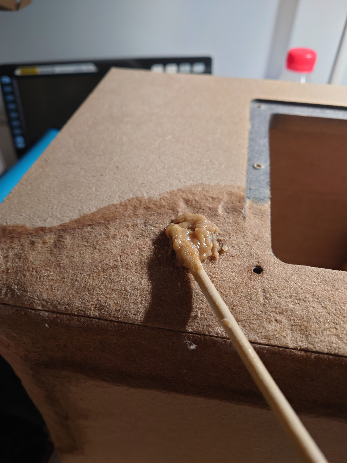
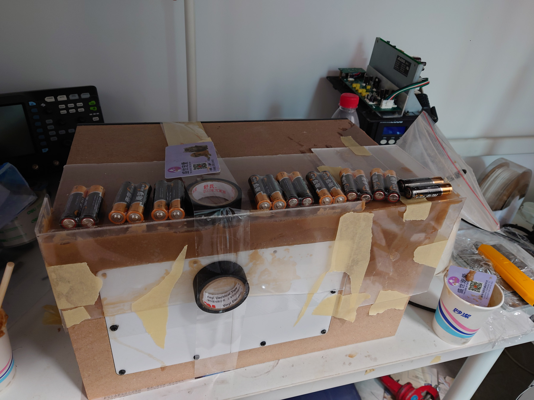
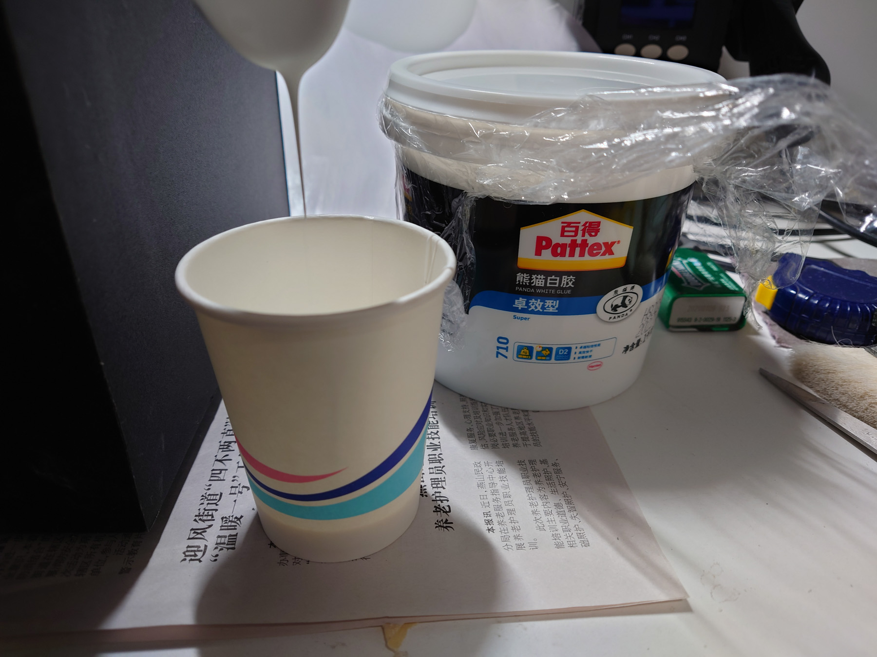
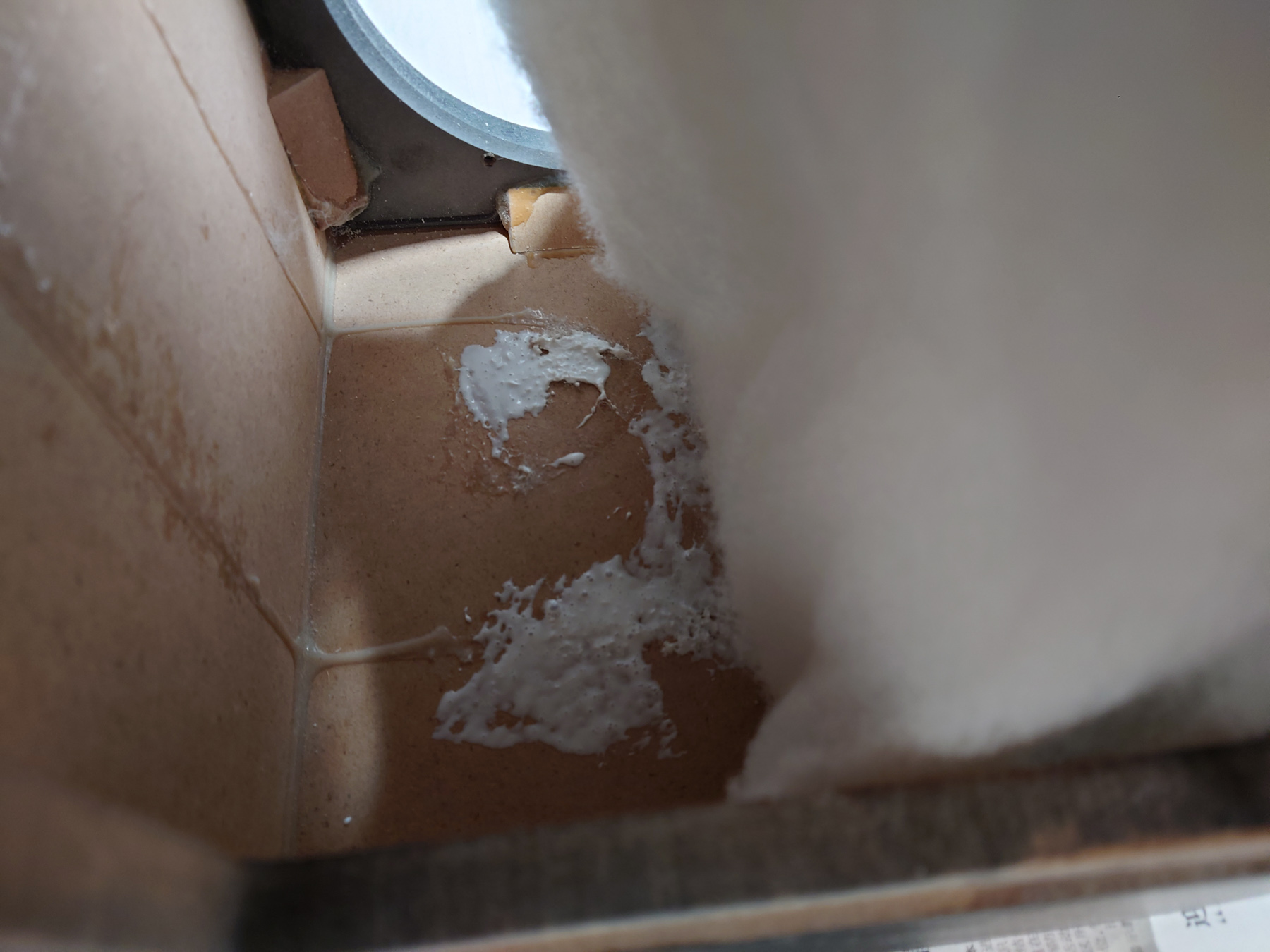
用环氧树脂加木粉重新做出外形
Reconstruct the cabinet using epoxy with wood flour
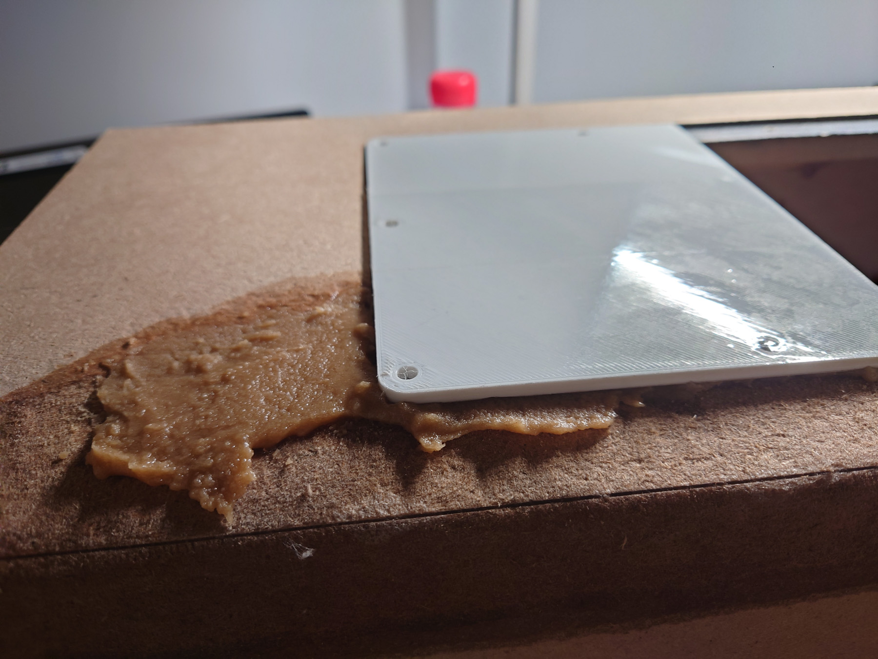
加简易的模板固定
Fix everything in place with some makeshift mold
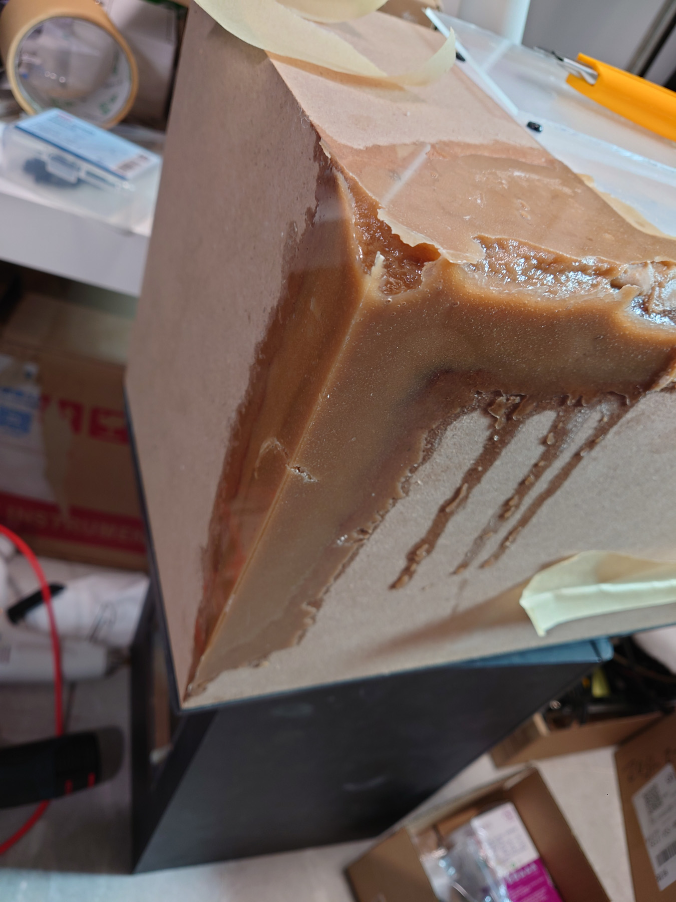
第一次浇注结果不是很完美,还需要再来一轮
First try yielded some cavities, so another round was required
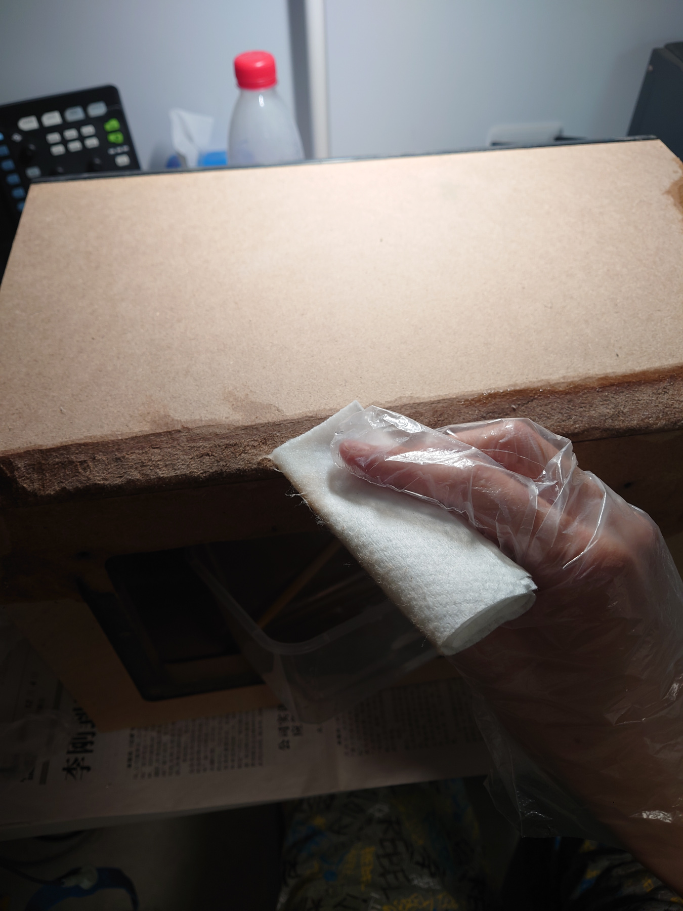
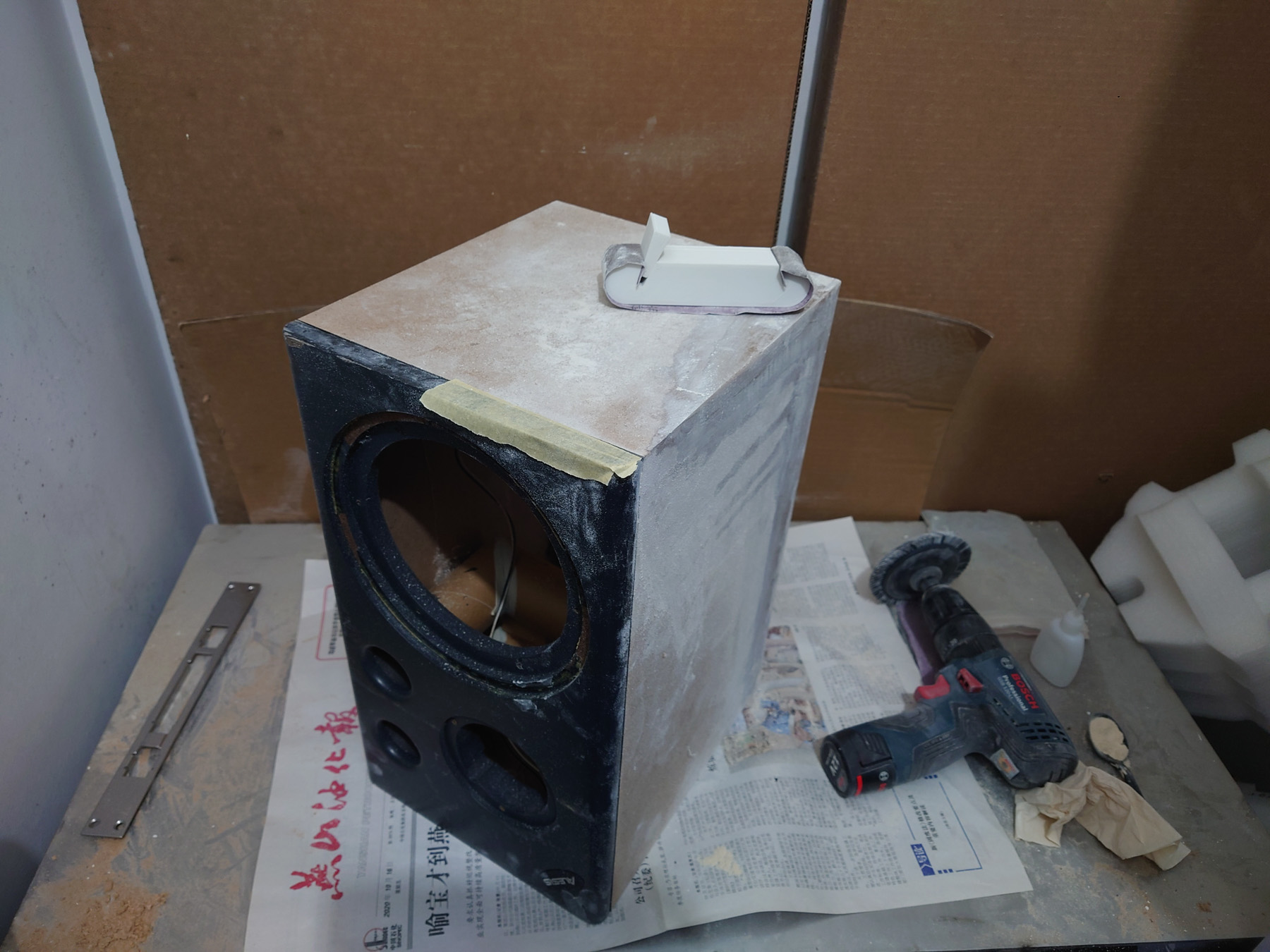
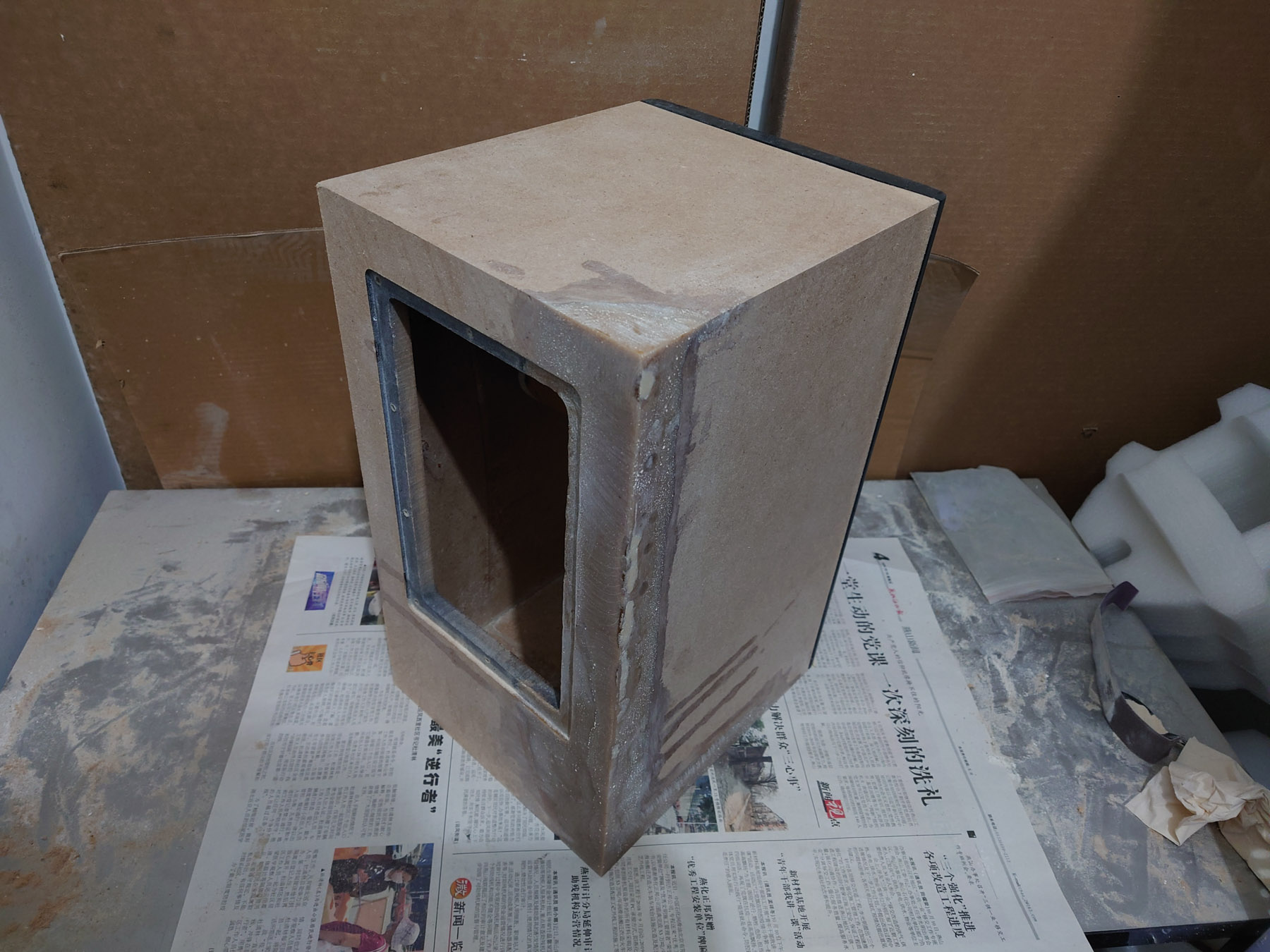
环氧干了之后进行打磨。打磨时为了快速修补不需要等48小时来让环氧固化,用502加木粉修补了一些地方。
I sanded it down after epoxy has cured. To fix some mistakes I used superglue and wood flour to avoid having to wait another 48 hours for epoxy to cure.
重新贴皮
Re-apply vinyl

喇叭单元维修 / Speaker Driver Repair
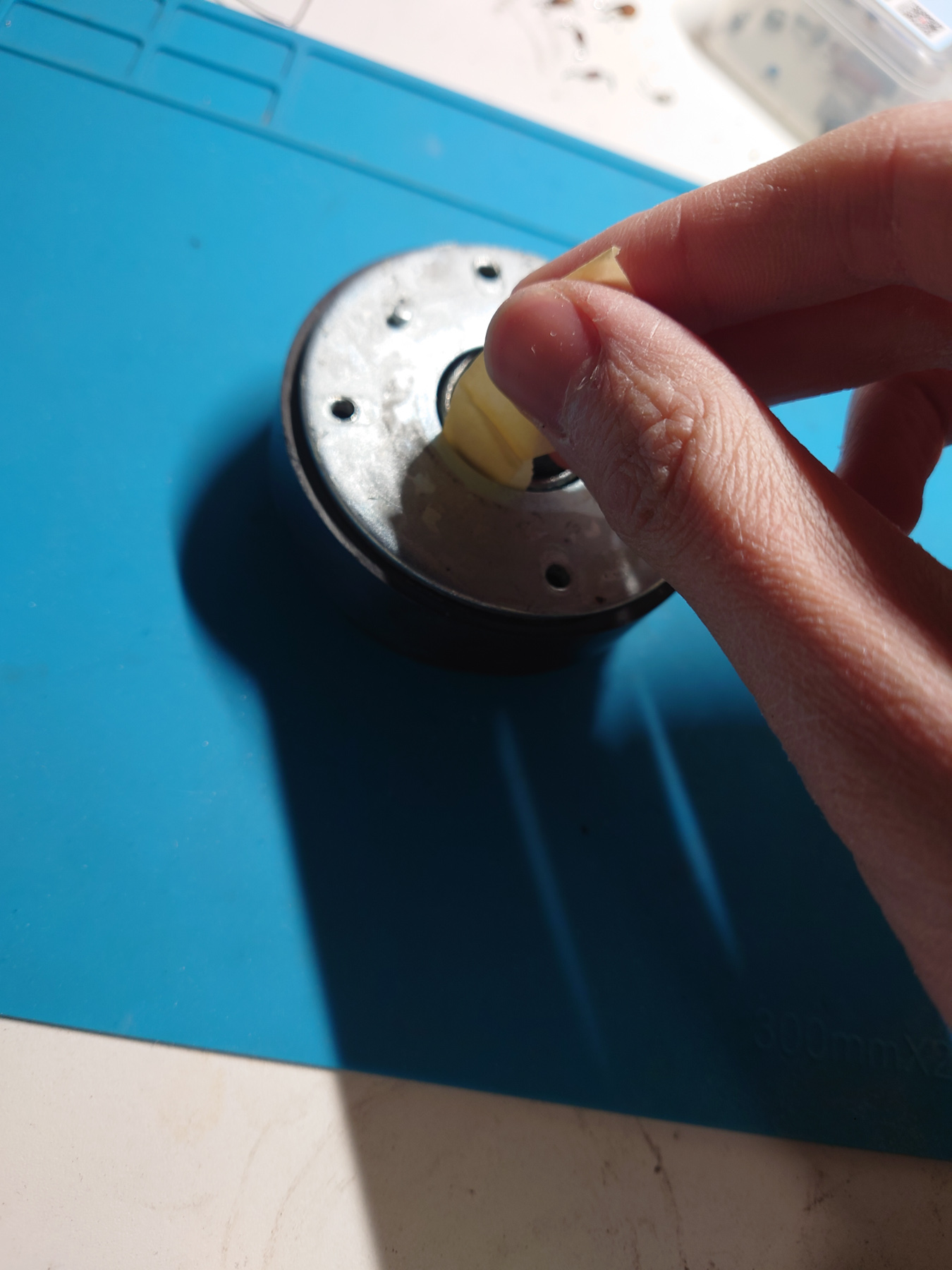
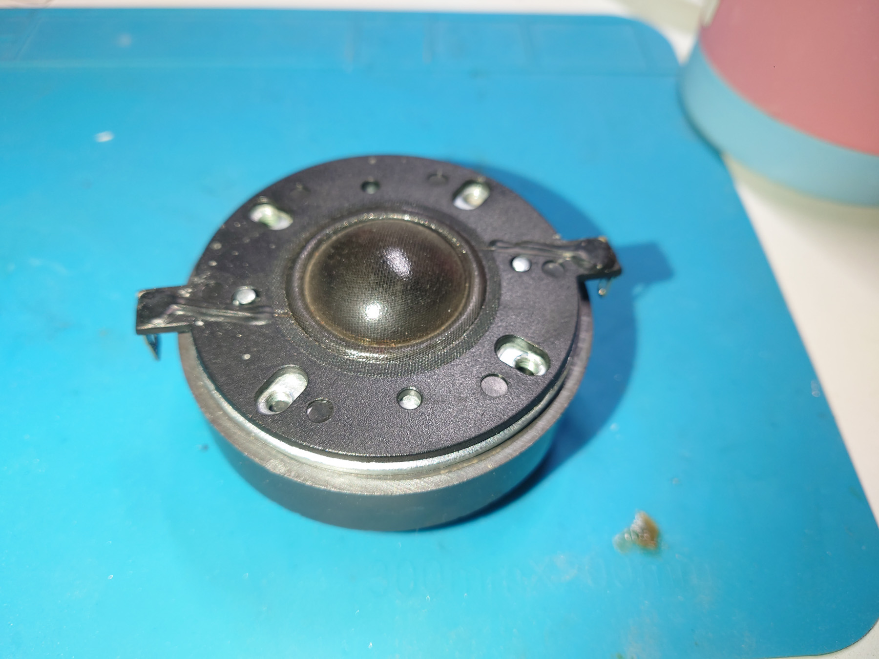
高音更换磁液 / Replace Ferrofluid in Tweeters
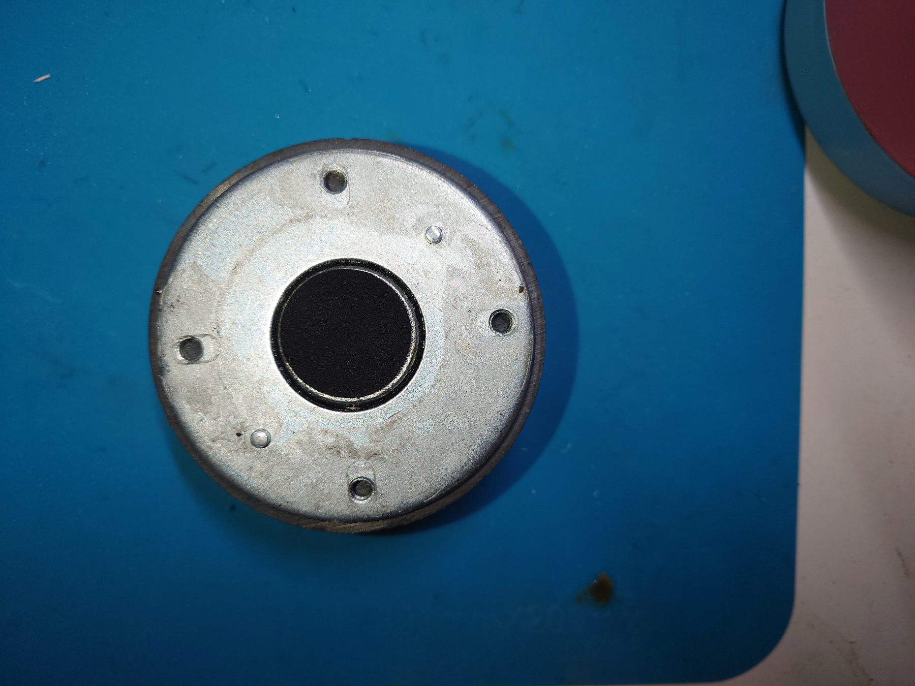
我从淘宝订购了低粘度的APG L11磁液。更换磁液时要拆开高音单元,清除所有之前的磁液,加入新的磁液。每个单元我加了大约100uL,也就是0.1毫升。更换参考了这个链接:https://speakerrepairshop.nl/en/instructions/replace-ferrofluid-in-tweeter/c-36
I ordered a small amount of APG L11 low viscousity ferrofluid. To replace FF in a tweeter, you take it apart, remove all old residues and put in new FF. I ended up putting about 100 micro-liter of FF into each tweeter. Reference: https://speakerrepairshop.nl/en/instructions/replace-ferrofluid-in-tweeter/c-36
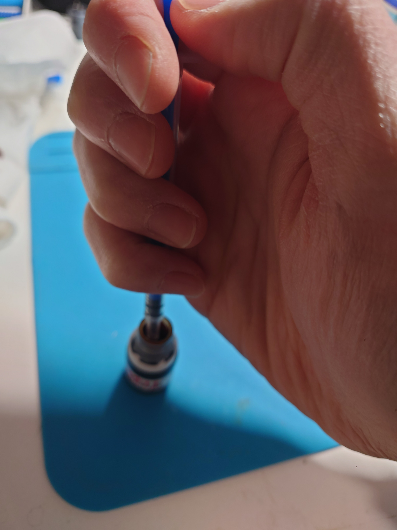
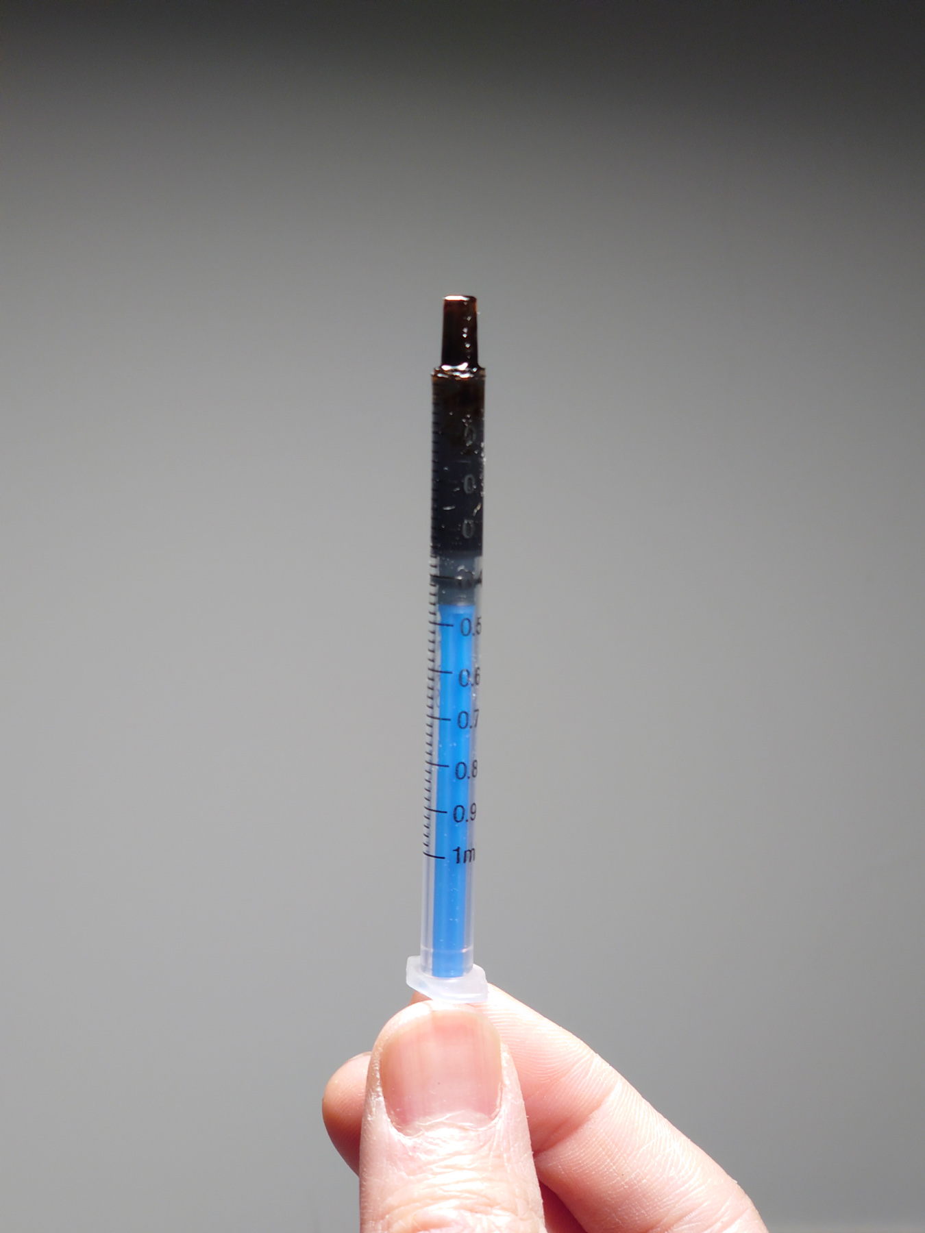
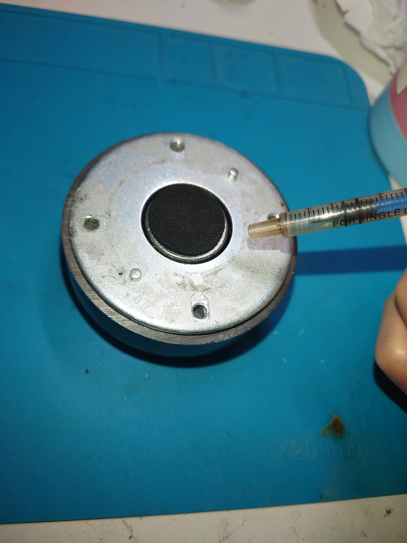
加磁液时,磁液会被自动吸进气隙里。这是加磁液的示意图。
When adding FF, it will be attracted into the air gaps automatically. This is what it looks like without any FF in the syringe.
组装 / Reassembling
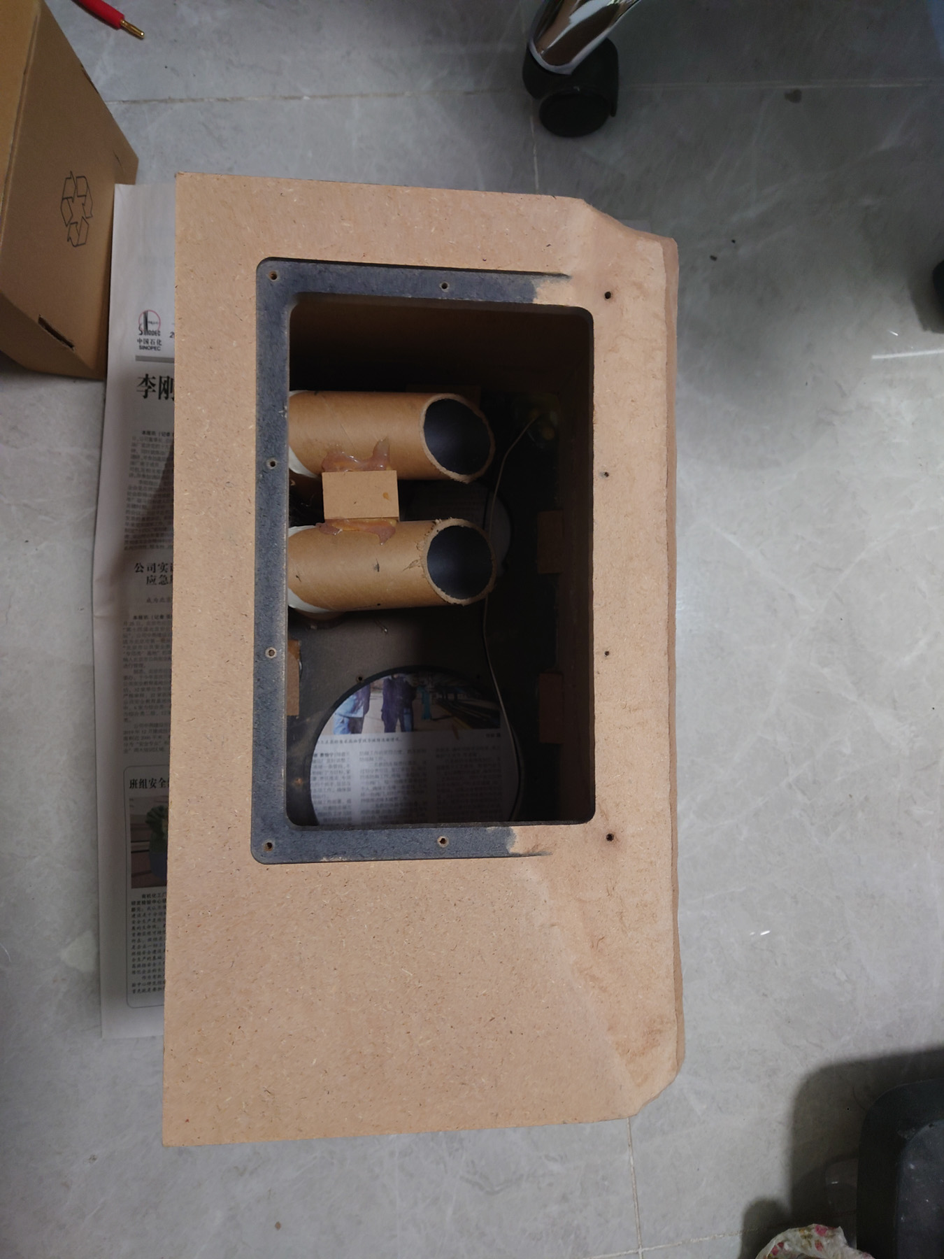
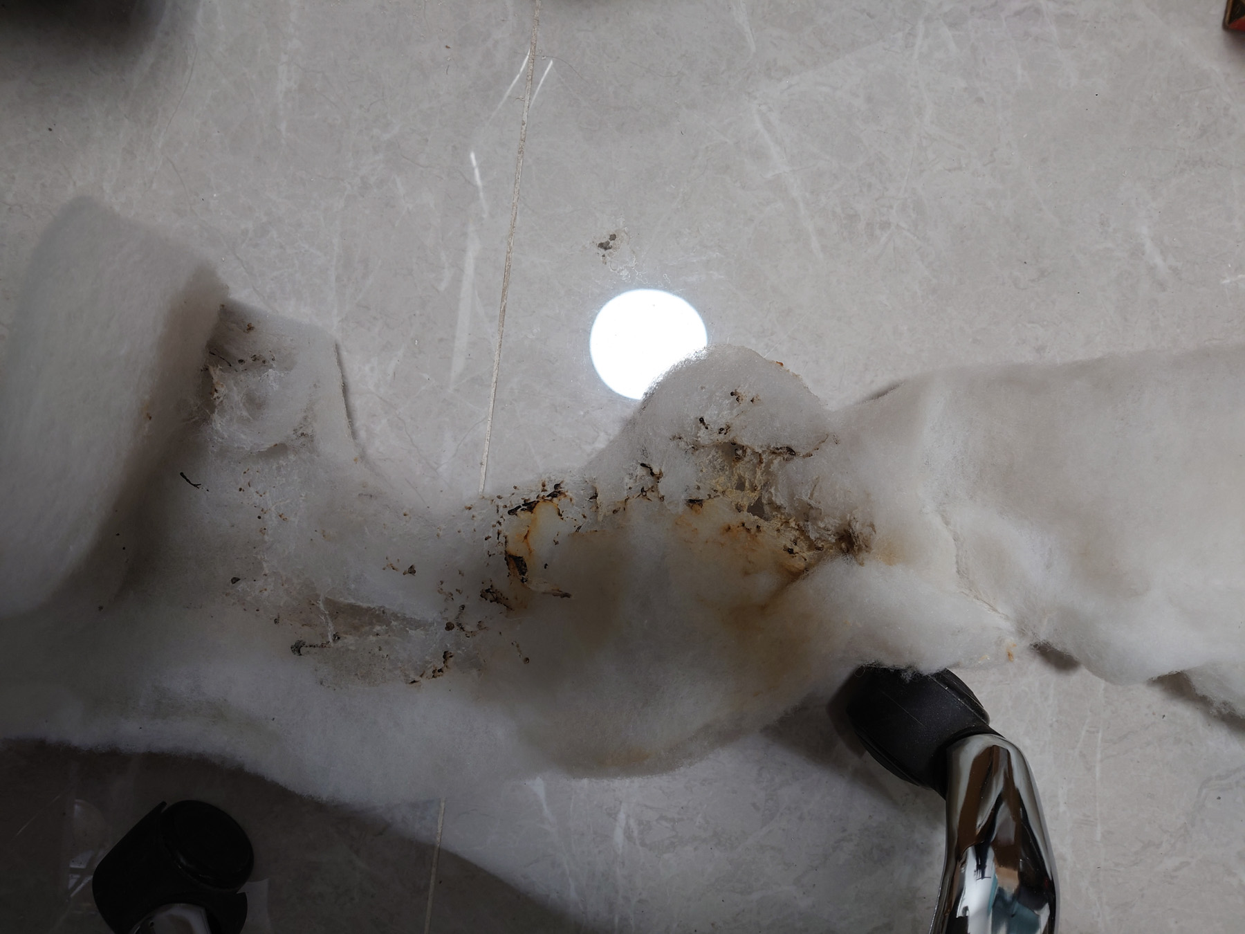
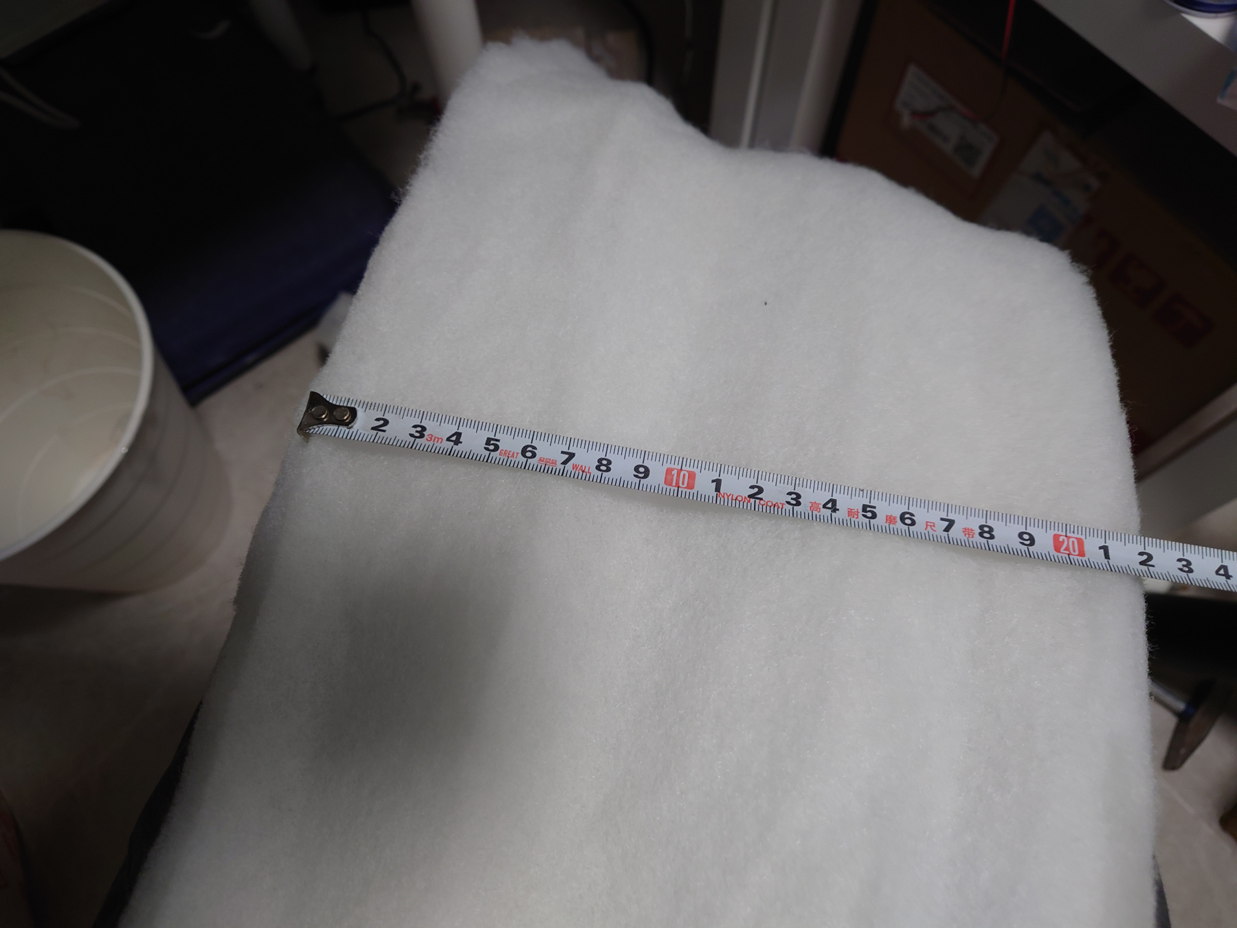
电路板烧毁的那一只内部的吸音棉被点燃烧掉了一些,另一只是箱体受损操作中也移除了吸音棉,所以两只都更换了新的吸音棉。
The polyfill in the speaker which has bad PSU was ignited when the PSU exploded. The other one has its polyfill removed during repairing of the cabinet. So both speakers were installed with new acoustic material.
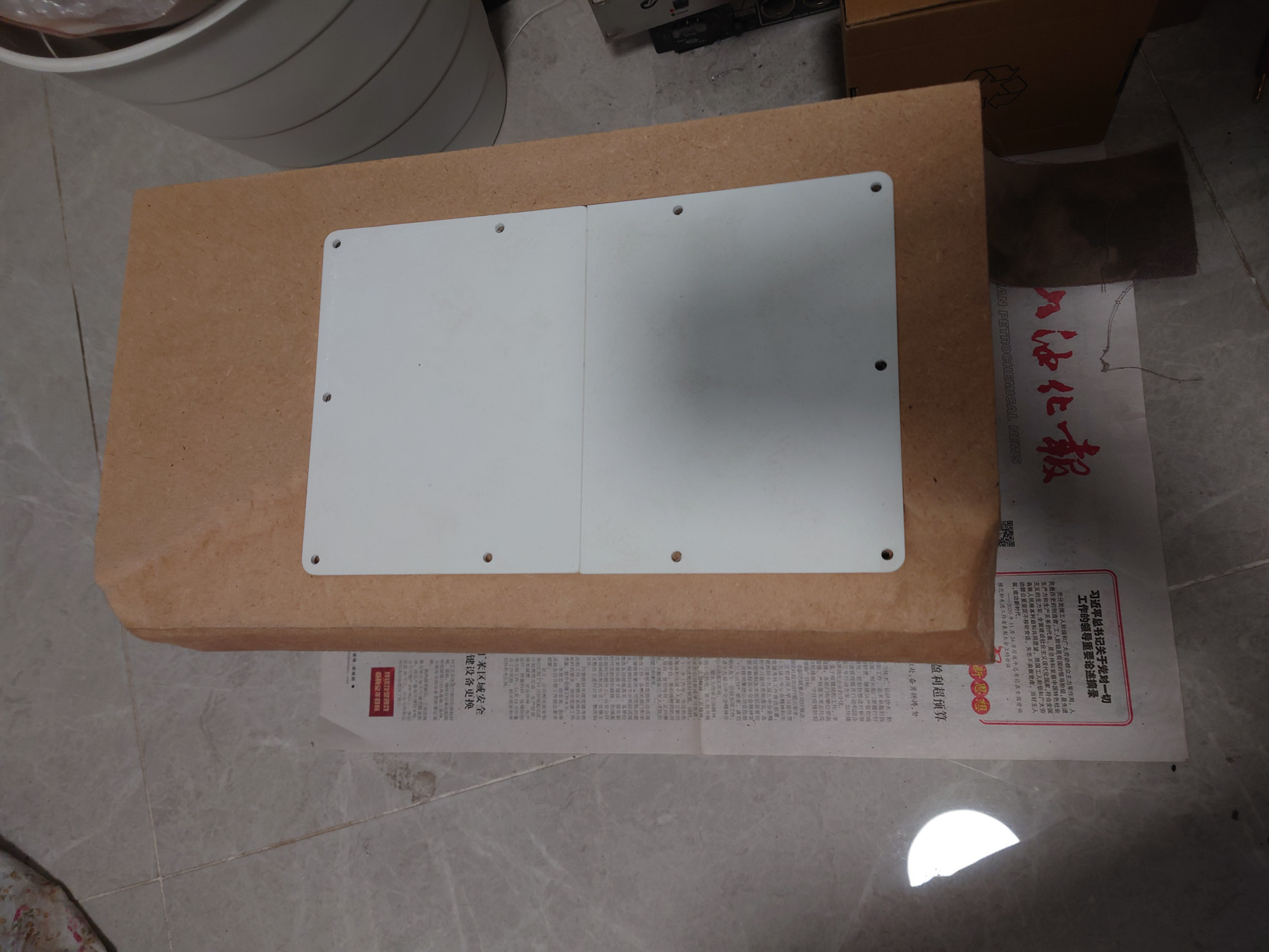
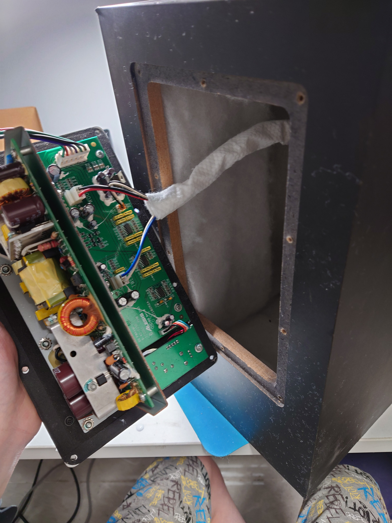
接下来将内部的线包裹好,接好功放板,将背板装回,在底部粘上EVA减震垫维修就全部完成了。功放单元用了新螺丝来固定,因为旧的缺失了一些。
Next is to wrap the wires inside the speakers, connect the amp, reinstall the back plate, put on EVA shock absorbing pads on the bottom side and that concluded all of the repair. New screws were used to mount the amp units as some were missing.
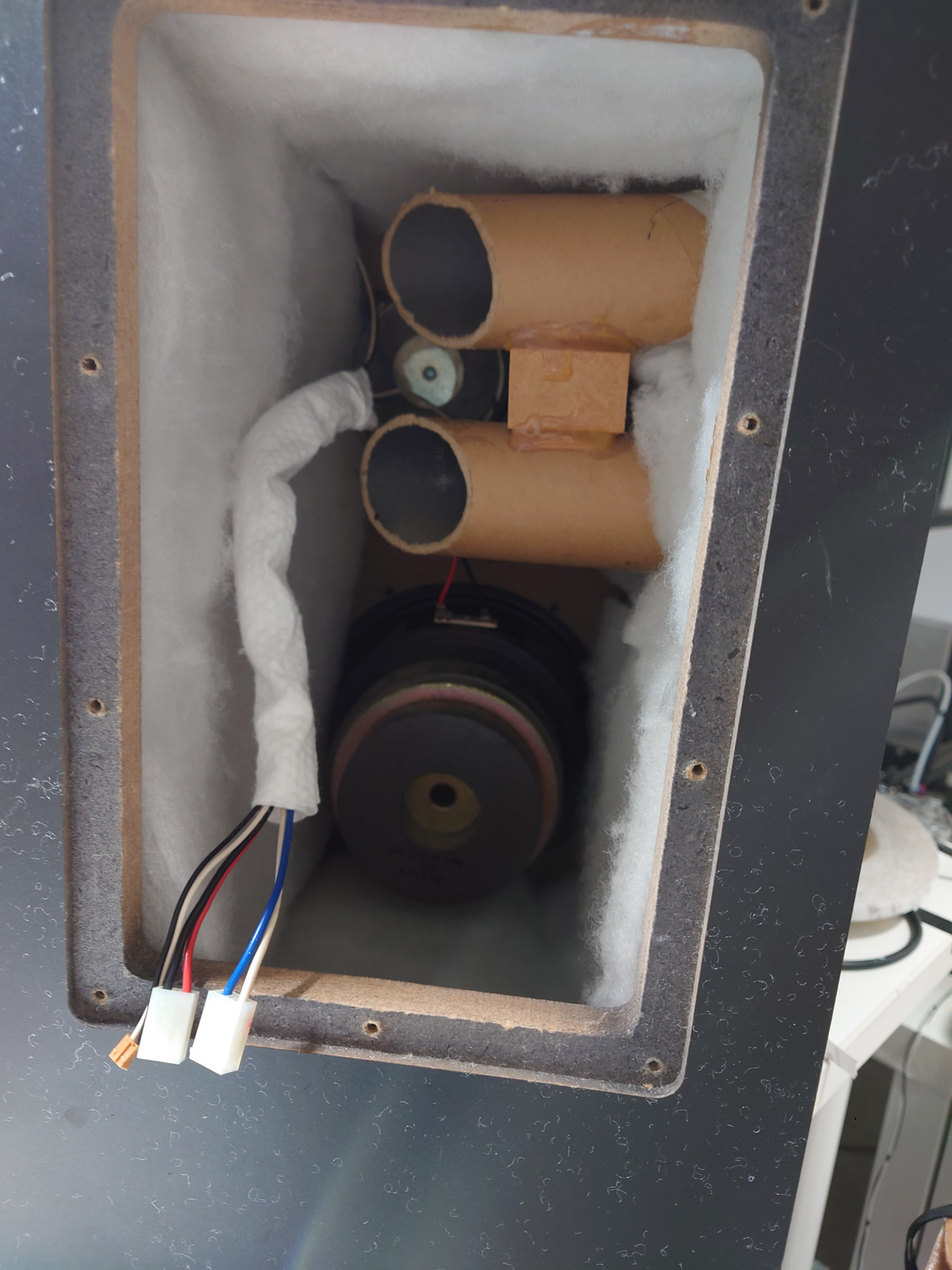
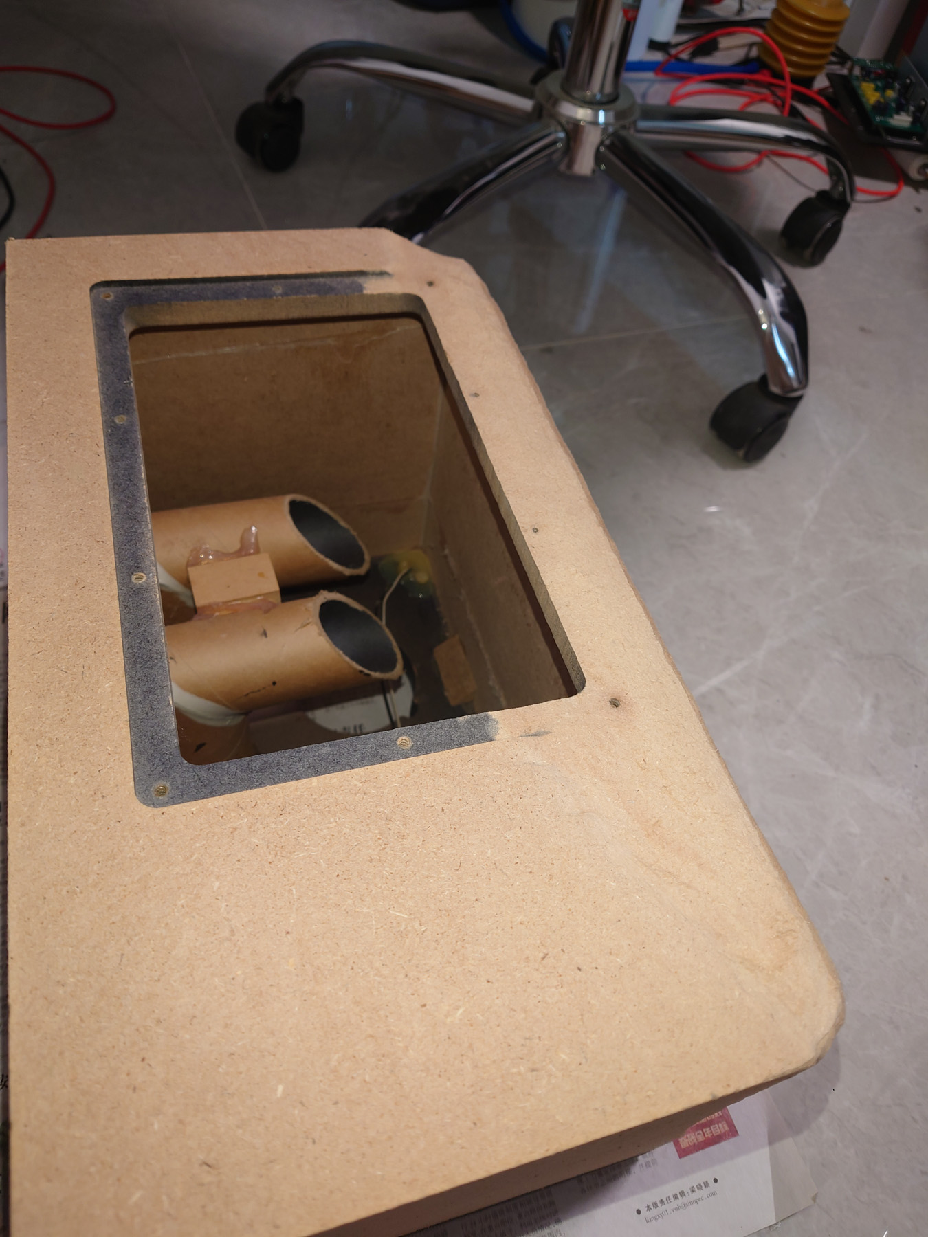
是的,倒相孔里是袜子
And yes, socks in the ports.
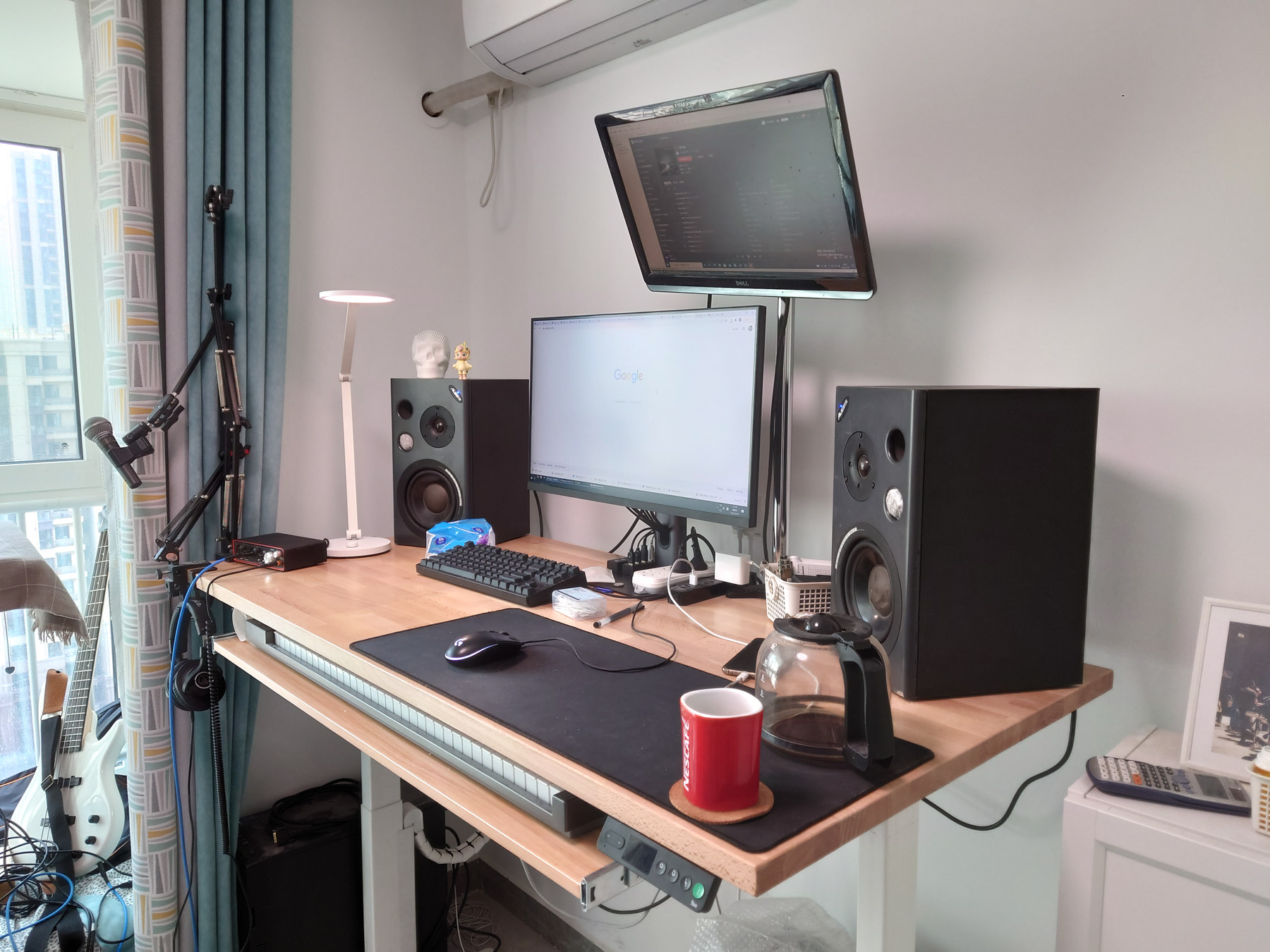
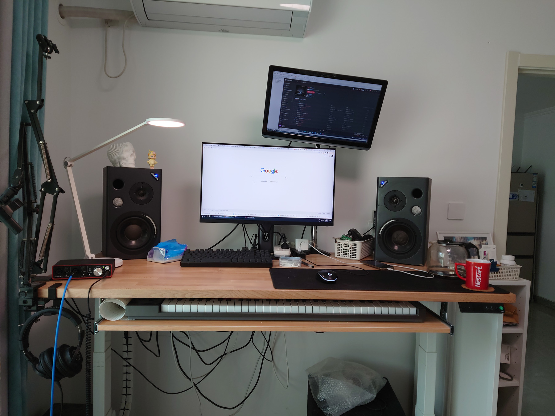
使用体验 / Experience Using the Speakers
到目前为止已经使用四个月了,没有任何问题。这对音箱声音比较均衡,低音对于6.5寸音箱来说非常充足了。
It has been 4 months after the repair, and there isn’t any problem. The sound of these speakers are well balanced, and bass content is very adequate for a woofer of this size.